
User Manual


GMC-I Messtechnik GmbH 41
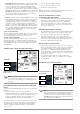
10.9 Earthing Resistance Measurement, Battery Operated – Selective (4-pole)
with Current Clamp Sensor and PRO-RE Measuring Adapter as Accessory (only MPRO & MXTRA)
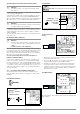
General
When measuring earthing resistance in systems with several par-
allel connected earth electrodes, total resistance of the earthing
system is measured.
Two earth spikes (auxiliary earth electrode and probe) are set for
this measurement. Measuring current is fed between the earth
electrode and the auxiliary earth electrode and voltage drop is
measured between the earth electrode and the probe.
The current clamp is positioned around the earth electrode to be
measured, and thus only that portion of the measuring current
which flows through the earth electrode is measured.
Connection
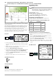
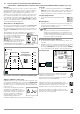
➭ Position the spikes for the probe and the auxiliary electrode at
least 20, respectively 40 meters from the electrode (see figure
above).
➭ Make sure that no excessively high contact resistances occur
between the probe and the ground.
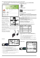
➭ Attach the PRO-RE adapter (Z501S) to the test plug.
➭ Connect the probes, the auxiliary electrode and the electrode
via the 4 mm banana plug sockets at the PRO-RE adapter.
In doing so, observe labeling on the banana plug sockets.
➭ Connect the Z3512A current clamp sensor to jacks 15 and 16 at
the test instrument.
➭ Attach the current clamp sensor to the earth electrode.
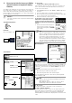
Select Measuring Function
Select Operating Mode
The selected operating mode is displayed inversely:
white battery icon against black background.
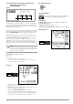
Set Parameters at Tester
❑ Measuring range: 200 Ω
Note
After switching to selective measurement, the AUTO
measuring range is activated automatically if a measuring
range of greater than 200 Ω had been selected.
❑ Connection type: selective
❑ Current clamp sensor transformer ratio:
1:1 (1 V/A,) 1:10 (100 mV/A), 1:100 (10 mV/A)
❑ Distance d (for measuring ρ
E
): irrelevant in this case
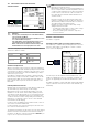
Set Parameters at Current Clamp Sensor
❑ Current clamp sensor measuring range: see table below
Selecting a Measuring Range at the Current Clamp Sensor
Important Instructions for Use of the Current Clamp Sensor
• Use only the Z3512A current clamp sensor for this measure-
ment.
•Use the clamp in the permanently connected state. The sensor
may not be moved during measurement.
• The current clamp sensor may only be used at an adequate
distance from powerful extraneous fields.
• Make sure that the current clamp sensor’s connector cable is
laid separate from the probe cables to the greatest possible
extent.
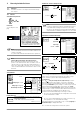
Start Measurement
PROFITEST MPRO, PROFITEST MXTRA
R
E
Tester Z3512A Clamp
Transforma-
tion Ratio
Parameter
Switch Measuring
Range
1:1
1 V / A
1 A / x 1 1 A
1:10
100 mV / A
10 A / x 10 10 A
1:100
10 mV / A
100 A / x 100 100 A