
User Manual


94 GMC-I Messtechnik GmbH
21.2 At which values should/must an RCD actually be tripped?
Requirements for Residual Current Devices (RCDs)
General Requirements
• Tripping must occur no later than upon occurrence of rated re-
sidual current (nominal differential current I
ΔN
).
and
• Maximum time to trip may not be exceeded.
Additional requirements due to influences on the tripping current range
and the point in time of tripping which have to be taken into consider-
ation:
• Residual current type or waveform:
This results in a reliable tripping current range.
• Mains type and line voltage:
This results in maximum tripping time.
• RCD variant (standard or selective):
This results in maximum tripping time.
Definitions of Requirements in the Standards
VDE 0100, part 600, which is included in all German standards col-
lections for electricians, applies to measurements in electrical sys-
tems. It plainly states: “The effectiveness of the protective mea-
sure is substantiated when shut-down occurs no later than upon
occurrence of rated differential current I
ΔN
.”
As a requirement for the measuring instrument manufacturer,
DIN EN 61557-6 (VDE 0413, part 6) unmistakably specifies:
“The measuring instrument must be capable of substantiating the
fact that the residual current which trips the residual current
device (RCD) is less than or equal to rated residual current.”
Comment
For all electricians, this means that during scheduled protective
measures testing after system modifications or additions to the
system, as well as after repairs or during the E-check conducted
after measurement of contact voltage, the trip test must be con-
ducted no later than upon reaching a value of, depending upon
the RCD, 10, 30, 100, 300 or 500 mA
How does the electrician react in the event that these values are
exceeded? The RCD is replaced!
If it was relatively new, a complaint is submitted to the manufac-
turer. And in his laboratory he determines: The RCD complies with
the manufacturer’s standard and is OK.
A look at the VDE 0664-10/-20/-100/-200 manufacturer’s stan-
dard shows us why:
Because the current waveform plays a significant role, the current
waveform used by the test instrument is also important.
Set residual current type or waveform at the test instrument:
It’s important to be able to select and take advantage of the cor-
responding settings at one’s own test instrument.
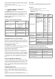
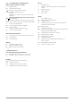
The situation is similar for breaking times. The new VDE 0100
part 410, should also be included in the standards collection.
Depending upon mains type and line voltage, it specifies breaking
times ranging from 0.1 to 5 seconds.
RCDs usually interrupt more quickly, but in some cases they can
take a bit longer. Once again, the ball is in the manufacturer’s
court.
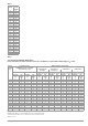
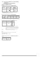
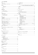
The following table is also included in VDE 0664:
Two limit values are highly conspicuous:
Standard Max. 0.3 s
Selective Max. 0.5 s
All of the limit values are already included in good test instru-
ments, or it’s possible to enter them directly and they’re displayed
as well!
Select or set limit values at the test instrument:
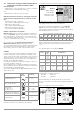
Type of Residual Current Residual
Current
Waveform
Allowable Tripping
Current Range
Sinusoidal alternating current 0.5 ... 1 I
ΔN
Pulsating direct current
(positive or negative half-waves)
0.35 ... 1.4 I
ΔN
Phase angle controlled
half-wave currents
Phase angle of 90° el
Phase angle of 135° el
0.25 ... 1.4 I
ΔN
0.11 ... 1.4 I
ΔN
Pulsating direct current superimposed
with 6 mA smooth, direct residual current
Max. 1.4 I
ΔN
+ 6 mA
Smooth direct current 0.5 ... 2 I
ΔN
System
50 V < U
0
≤
120 V
120 V < U
0
≤
230 V 230 V < U
0
≤
400 V
U
0
> 400 V
AC DC AC DC AC DC AC DC
TN
0.8 s 0.4 s 5 s 0.2 s 0.4 s 0.1 s 0.1 s
TT
0.3 s 0.2 s 0.4 s 0.07 s 0.2 s 0.04 s 0.1 s
Variant
Residual
Current
Type
Breaking Time at
Alternating
residual
current
1 x I
ΔN
2 x I
ΔN
5 x I
ΔN
500 A
Pulsating
direct residual
current
1.4 x
I
ΔN
2 x 1.4 x I
ΔN
5 x 1.4 x I
ΔN
500 A
Smooth, direct
residual
current
2 x
I
ΔN
2 x 2 x I
ΔN
5 x 2 x I
ΔN
500 A
Standard
(undelayed)
or briefly
delayed
300 ms Max. 0.15 s Max. 0.04 s Max. 0.04 s
Selective 0.13 ... 0.5 s 0.06 ... 0.2 s 0.05 ... 0.15 s 0.04 ... 0.15 s
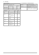
Negative half-wave
Positive half-wave
Waveform:
Negative direct current
Positive direct current