
User Manual


GMC-I Messtechnik GmbH 95
Tests for electrical systems include “visual inspection”, “testing”
and “measurement”, and thus may only be conducted by experts
with appropriate work experience.
In the final analysis, the values from VDE 0664 are technically
binding.
21.3 Testing Electrical Machines per DIN EN 60204 –
Applications, Limit Values
The PROFITEST 204+ test instrument has been developed for the
testing of electrical machines and controllers. After a revision to
the standard in 2007, measurement of loop impedance is now
additionally required. Measurement of loop impedance, as well as
other measurements required for the testing of electrical
machines, can be performed with test instruments from the
PROFITEST MASTER series.
Comparison of Tests Specified by the Standards
Uninterrupted Connection of a Protective Conductor
Uninterrupted connection of a protective conductor system is
tested here be using an alternating current of 0.2 to 10 A with a
line frequency of 50 Hz (= low-resistance measurement). Testing
must be conducted between the PE terminal and various points
within the protective conductor system.
Loop Impedance Measurement
Loop impedance Z
L-PE
is measured and short-circuit current I
K
is
ascertained in order to determine if the breaking requirements for
protective devices have been fulfilled (see section 8).
Insulation Resistance Measurement
All of the active conductors in the primary circuit are short-cir-
cuited at the machine (L and N, or L1, L2, L3 and N) and mea-
sured against PE (protective conductor). Controllers or machine
components which are not laid out for these voltages (500 V DC)
can be disconnected from the measuring circuit for the duration
of the measurement. The measured value may not be any less
than 1 MOhm. The test can be subdivided into separate seg-
ments.
Voltage Tests (with PROFITEST 204HP/HV only)
The electrical equipment of the machine under test must with-
stand a test voltage of twice its own rated voltage value or 1000
V~ (whichever is largest) applied between the conductors of all
circuits and the protective conductor system for a period of at
least 1 second. The test voltage must have a frequency of 50 Hz,
and must be generated by a transformer with a minimum power
rating of 500 VA.
Residual Voltage Measurement
The EN 60204 standard specifies that after switching supply
power off, residual voltage must drop to a value of 60 V or less
within 5 seconds at all accessible, active components of a
machine to which a voltage of greater that 60 V is applied during
operation.
If conductors are exposed, the residual voltage must have
dropped to a value of 60 V or less within a time span of 1 second.
Function Test
The machine is operated with nominal voltage and tested for cor-
rect functioning, in particular with regard to safety functions.
Special Tests
• Pulse control mode for troubleshooting (with
PROFITEST 204HP/HV only)
• Protective conductor test with 10 A test current (with
PROFITEST 204+ only)
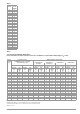
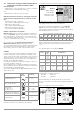
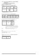
Limit Values per DIN EN 60204, Part 1
Overvoltage Protection Device Characteristics for
Limit Value Selection for Protective Conductor Testing
Tests per DIN EN 60204, part 1
(machines)
Tests per DIN EN 61557
(systems)
Meas.
Func-
tion
Uninterrupted connection of a
protective conductor
Part 4: resistance of:
– Ground conductor
– Protective conductor
– Bonding conductor
RLO
Loop impedance Part 3: loop impedance ZL-PE
Insulation resistance Part 2: insulation resistance RINS
Testing for dielectric strength
Part 14: Equipment for testing the
safety of electrical equipment of ma-
chinery
—
Protection against residual
voltage
Part 14: Equipment for testing the
safety of electrical equipment of ma-
chinery
Ures
Function test ——
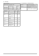
Measurement Parameter Cross-
Section
Standard
Value
Protective conduc-
tor measurement
Test Duration 10 s
Limit value for protective
conductor resistance
based on phase conductor
cross-section and charac-
teristics of the overvoltage
protection device (calcu-
lated value)
1.5 mm²
2.5 mm²
4.0 mm²
6.0 mm²
10 mm²
16 mm²
25 mm² L
(16 mm² PE)
35 mm² L
(16 mm² PE)
50 mm² L
(25 mm² PE)
70 mm² L
(35 mm² PE)
95 mm² L
(50 mm² PE)
120 mm² L
(70 mm² PE)
500 mΩ
500 mΩ
500 mΩ
400 mΩ
300 mΩ
200 mΩ
200 mΩ
100 mΩ
100 mΩ
100 mΩ
050 mΩ
050 mΩ
Insulation resistance
measurement
Nominal voltage 500 V DC
Resistance limit value ≥ 1MΩ
Leakage current
measurement
Leakage current 2.0 mA
Protection against
residual voltage
Discharge time after switching off supply
power
5s
Discharge time after exposing
conductors
1s
Testing for dielectric
strength
Test voltage 2 x U
N
or 1 kV
Test voltage frequency 50 Hz or 60 Hz
Test duration 1 s
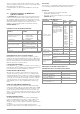
Breaking Time, Characteristics Available for Cross-Section
Fuse breaking time: 5 s All cross-sections
Fuse breaking time: 0.4 s 1.5 through 16 sq. mm
Circuit breaker, characteristic B
Ia = 5 x In – breaking time: 0.1s
1.5 through 16 sq. mm
Circuit breaker, characteristic C
Ia = 10x In – breaking time: 0.1s
1.5 through 16 sq. mm
Adjustable circuit breaker
Ia = 8 x In - break time: 0.1s
All cross-sections