
Datasheet


SECUTEST BASE / PRO and SECULIFE ST BASE(25)
Test Instruments for
Measuring
Electrical Safety of Devices
2 GMC-I Messtechnik GmbH
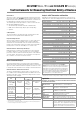
Overview of Features Included with SECUTEST BASE, SECUTEST PRO and SECULIFE ST BASE(25) Test Instruments
1
10 A/25 A-R
PE
measurements are only possible with line voltages of 115/230 V
and line frequencies of 50/60 Hz.
2
Voltage mesurement inputs only with SECUTEST PRO (or device with Feature I01) and
SECULIFE ST BASE(25)
3
Terminal for 2
nd
test probe for 2-pole measurement only with SECUTEST PRO (or de-
vice with Feature H01) and
SECULIFE ST BASE(25)
4
Measurement of time to trip not possible in IT systems
5
No checking for reversed polarity takes place when the EL1 adapter is used.
Key
Alternative =
alternative measurement
(equivalent leakage current
measurement)
Differential = differential current measurement
Direct = direct measurement
LN(TS) = short-circuited conductors L and N of test socket
P1 = measurement with test probe P1
P1-P2 = 2-pole measurement with test probe P1 & P2
PE-P1 = measurement between PE and test probe P1
PE(TS) = protective conductor of test socket
PE(Mains) = protective conductor of mains terminal
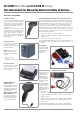
Display with Selectable Language
The display panel consists of a backlit, color multi-display at
which menus, setting options, measurement results, instructions
and error messages, as well schematic and wiring diagrams
appear.
The display and user prompting can be set to the desired lan-
guage depending on the country in which the test instrument is
used.
Data Entry
Data can be entered, for example, via a barcode reader con-
nected to the USB port, a RFID scanner, a USB keyboard, or via
the softkey keyboard when it appears at the display.
The touch screen of SECUTEST PRO (or devices with Feature E01)
and SECULIFE ST BASE(25) allows for the convenient entry of data
and comments while menu control is still based on softkeys.
Creating a Database
A complete test structure with data regarding customers, build-
ings*, floors*, rooms* and test objects can be created in the test
instrument. This structure makes it possible to assign single mea-
surements or test sequences to devices under test belonging to
various customers. Manual single measurements can be grouped
together into a so-called “manual sequence”.
The SECUTEST PRO and SECULIFE ST BASE(25) test instruments and
those instruments with database expansion (Feature KB01)
enable the user to prepare a test structure by means of the
IZYTRONIQ software at the PC for subsequent transmission to the
test instrument.
*only with SECUTEST PRO or with database expansion (Feature KB01) and SECULIFE
ST BASE(25)
Switch
Set-
ting
Measuring Function,
Test Current/Voltage
Measurement
Type
Connection Type
Single measurements, rotary switch level: green
R
PE
R
PE
Protective conductor resistance
PE(TS) - P1 passive
PE(TS) - P1 active
PE(Mains) - P1
PE(Mains) - P1 Clamp
2
P1 - P2
3
I Test current (200 mA)
SECUTEST BASE10/PRO:
and
SECULIFE ST BASE
10 A
1
(Feature G01)
&
SECULIFE ST BASE25
: 25 A
1)
(
Feature
G02)
RISO
R
ISO
Insulation resistance LN(TS) - PE(TS)
LN(TS) - P1
P1 - P2
3
PE(Mains) - P1
PE(TS) - P1
LN(TS) - P1//PE(TS)
U
ISO
Test voltage
IPE
I
PE
Protective conductor current, RMS value Direct
Differential
Alternative
AT3-Adapter
2
Clamp
2
I
PE~
AC component
I
PE=
DC component
U
LN
Test voltage
IB
I
T
Touch current, RMS value Direct
Differential
Alternative (P1)
Permanent connection
Alternative (P1–P2)
I
T~
AC component
I
T=
DC component
U
LN
Test voltage
IG
I
E
Device leakage current, RMS value Direct
Differential
Alternative
AT3-Adapter
2
Clamp
2
I
E~
AC component
I
E=
DC component
U
LN
Test voltage
IA
I
A
Leakage current from the application part,
RMS value
Direct (P1)
Alternative (P1)
Permanent conn. (P1)
U
A
Test voltage
IP
I
P
Patient leakage current, RMS value
Direct (P1)
Permanent conn. (P1)
I
P~
AC component
I
P=
DC component
U
LN
Test voltage
U
U
Probe voltage, RMS
PE - P1
PE - P1 (with mains*)
* polarity preset
U
~
Alternating voltage component
U
=
Direct voltage component
U
Measurement Voltage RMS
2
V – COM
V – COM (with mains)
U
~
Alternating voltage component
2
U
=
Direct voltage component
2
ta
4
t
B
PRCD time to trip
for 30 mA PRCDs
U
LN
Line voltage at the test socket
P Function test at the test socket
Polarity preset
I Current between L and N
U Voltage between L and N
f Frequency
P Active power
S Apparent power
PF Power factor
Probe measuring functions
EL1
Extension cords with adapter:
continuity, short-circuit, polarity (wire reversal
5
)
EL1 adapter
AT3-IIIE adapter
VL2E adapter
EXTRA
Reserved for expansion during the course of software updates
°C
Temperature measurement
2
with Pt100/Pt1000
V – COM
IZ Measurement of current at clamp with
current clamp sensorn
V – COM
Switch
Setting
Standard Measurement Type, Connection Type
Automated test sequences, rotary switch level: orange
Preconfigured (freely configurable) test sequences – Delivery Status
A1
VDE 0701-0702 Passive measuring method, test socket
A2
VDE 0701-0702 Active measurement type, test socket
A3
VDE 0701-0702-IT
Parameters configuration for EDP (active)
A4
IEC 62353 (VDE 0751) Passive measurement type
A5
IEC 62353 (VDE 0751) Active measurement type
A6
IEC 60974-4 Connection type: test socket
A7
IEC 60974-4 Connection type: AT16-DI/AT32-DI
A8
VDE 0701-0702
VDE 0701-0702, measurement type Extension Cord
test (RPE, RISO), EL1/VL2E/AT3-IIIE adapter
AUTO
VDE 0701-0702 Active measurement type, test socket