
Operation Manual


1-6
PX5 Controls, Indicators, and Connectors, continued
Top and Side
views
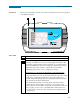
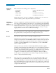
The top (circuit connection) view features the input voltage and current connectors.
The left side contains the optical interface port. The right side contains the AC adapter
input connector. Both sides have rings for attaching the supplied carrying strap. See
below for descriptions of the top and side connectors.
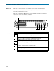
Parts table
Part Function
1 CH A, + Differential Voltage Input Connector; color red.
2 CH A, - Differential Voltage Input Connector; color white.
3 CH A, PROBE, Current Input Connector.
4 CH B, + Differential Voltage Input Connector; color yellow.
5 CH B, - Differential Voltage Input Connector; color white.
6 CH B, PROBE, Current Input Connector.
7 CH C, + Differential Voltage Input Connector; color blue.
8 CH C, - Differential Voltage Input Connector; color white.
9 CH C, PROBE, Current Input Connector.
10 CH D, + Differential Voltage Input Connector; color grey.
11 CH D, - Differential Voltage Input Connector; color white.
12 CH D, PROBE, Current Input Connector.
13 Optical Serial Data Port
14 AC Adapter/Battery Charger Input Connector.
1 2 3 5 6 7 8 9 10 11 124
13 14