
Operation Manual

E-5
APPENDIX E/ Common Circuit Connections
Verifying Voltage and Current Connections
Introduction
Correct voltage and current connection of single phase, split phase, or polyphase
connections can be verified using phasor diagrams. Phasor diagrams are graphic
representations that show the magnitude and angular relationship of voltage and current
for each phase of a monitored connection. Each connection diagram on the following
pages shows the correct voltage and current phasor diagrams (for resistive loads) for
that circuit.
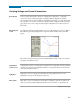
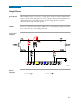
Displaying the
screen
To display the Voltage and Current Phasor screen, from the Home screen press Phasor.
The following screen depicting Positive Sequence 3 Phase Delta resistive load will
appear.
The touch screen Demo button presents an animated phasor demo rotation for resistive,
capacitive and inductive loads.
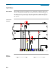
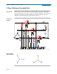
Single Phase
resistive load
A single phase voltage or current phasor is displayed as a single line showing a channel
reference at 0 degrees and a magnitude relative to its measured value. An arrow head
on the line indicates direction.
Split phase
Split phase vectors are displayed as dual lines showing channel references and
magnitudes and opposite (180 degrees) directions.
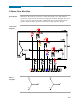
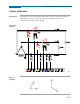
Three phase
Three phase vectors are displayed as three lines, 120 degrees apart in a resistive load
(unity power factor). Phase displacement will occur in a reactive or capacitive load.
Continued on next page
MARK241