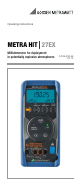
Operating Instructions METRA HIT27EX Milliohmmeter for deployment in potentially explosive atmospheres 3-349-336-49 7/2.
1 chapter 5 2 chapter 3 3 chapter 6 4 chapter 4 5 chapter 7.2 6 chapter 7.3 7 chapter 7.
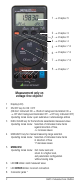
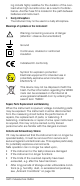
1 2 3 4 5 6 8 7 Symbols used in the Digital Display 1 Main display with decimal point 2 GB Auxiliary displays 3 : Milliohmmeter in continuous operation, ON blinks at transmission frequency in transmission mode 4 REM: Memory mode operation, disappears after communication via the interface is ended by means of key or switch operation 5 ZERO: Zero balancing 6 MAN: Manual measuring range selection 7 Unit of measure (if blinking, refer to chapter 11 on page 33) 8 : Low battery voltage, repl
Contents Page 1 Application .............................................................. 5 2 Safety Features and Precautions ............................ 5 3 Initial Start-Up ......................................................... 8 4 Selecting Measuring Functions and Measuring Ranges .10 4.1 4.2 4.3 Automatic Measuring Range Selection ................................ 10 Manual Measuring Range Selection .................................... 10 Quick Measurements ...............................
1 Application METRA HIT27EX is a milliohmmeter with 4-pole measurement, which is designed for deployment in potentially explosive environment. In accordance with directive 94/9/CE dated 23th March 1994 the device is approved for being used in explosive, gaseous atmospheres (IIA T4) with ambient temperatures between –10 °C and +50 °C.
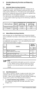
– – – Measurements may only be performed within the indicated ambient conditions. See page 29 for operating temperature range and relative humidity. The instrument may not be used in a dusty atmosphere. No maintenance operation may be performed in potentially explosive atmospheres (cleaning, replacement of batteries, opening the device, etc.) Observe the following safety precautions: • Type-tested Housing The milliohmmeter may not be operated with open housing.
ing circuits highly resistive for the duration of the overload when high currents occur as a result of a disturbance. Another fuse F2 is located in the path between batteries and instrument. Dusty Atmosphere The instrument may not be used in a dusty atmosphere.
3 Initial Start-Up Insert Batteries Warning! Remove the instrument from the potentially explosive environment before opening. Only use the included type-tested batteries, as indicated in the Characteristic Values. Refer to chapter 10.1 regarding correct battery installation.
Shutdown is acknowledged with two, brief acoustic signals. Switching the Milliohmmeter Off Automatically – „SLEEP MODE“ The instrument is switched off automatically if none of the keys are activated for approximately 10 minutes. Shutdown is acknowledged with a brief acoustic signal. Transmission mode: In this case, checking is first performed to determine whether or not the sampling rate has been set to a value of greater than 10 s.
4 Selecting Measuring Functions and Measuring Ranges 4.1 Automatic Measuring Range Selection The milliohmmeter is equipped with auto-ranging for all measuring ranges. Auto-ranging is active as soon as the instrument is switched on. The instrument automatically selects the measuring range which allows for highest possible resolution for the applied quantity.
• via DATA function, see chapter 6.1. After the first measurement, the proper measuring range will be automatically determined so that measurements are performed more rapidly from the second measured value onwards. With both functions, the established measuring range is maintained for the subsequent series mode measurments. 5 Triple Digital Display The three digital displays (1 main display and 2 auxiliary displays) show the measured value with decimal and plus or minus sign.
6 Measured Value Storage The METRA HIT27EX provides two entirely different options for storing data: • Measured Value Memory – DATA Key Function: Each time the DATA key is pressed and a measuring point is contacted, a measured value is stored (see chapter 6.1). • Memory Mode Operation – STORE Menu Function: After activating the STORE menu function, all measured values are saved in accordance with the selected sampling rate.
The red LED ERROR lights up as long as no contact has been established between the test probes and the measuring point. The green LED OK continues to light up when a valid measured value has already been stored. Prior to contacting the next measuring point, the function DATA must be activated once more by pressing the DATA key. The message data blinks and indicates readiness for acquiring the next measured value. ERROR OK 0.L blinks openl DATA Acoustic signal 1x ERROR OK 0.L 0.l data Meas.
automatically adjusted, the measuring ranges should not be changed manually. The DATA function is deactivated if the DATA|CLEAR key is pressed and held (approx. 1 s) or by switching the instrument off and back on again. 7 Milliohm Measurement (4-Pole-Measurement) 7.1 Compensation of Cable Resistance Electrical resistance is a dipole quantity which can generally only be measured using two poles.
7.2 Thermovoltage Compensation Thermovoltages which occur as a result of material and temperature differences may distort measurement results. For this reason, the instrument is equipped with automatic thermovoltage compensation in the relevant measuring ranges. After switching on the milliohmmeter, „termoc“ is displayed, indicating that an automatic thermovoltage compensation for the 30 mand 300 mmeasuring ranges will be performed in the background for all future measurements.
7.3 Milliohm Measurement with 100 mA DC [m] ➭ Make sure that the device under test is voltage-free. ➭ Connect the device under test as shown. I– U– m U+ I+ Note: When using KC27 or KC4 always set red probe plug at U+ or U–, respectively. Measurement Cables, KC27 or KC4 Overall Measuring Range: Rx – Voltage Drop m: 0.01 m 30 + Measuring Current KC4 Kelvin clips and KC27 Kelvin probes (available as accessories) allow for easy, correct connection.
8 Using the Menus – from the Initial InFO Menu to Operating and Measuring Parameters Menu-driven operation via the initial „1NF0“ menu allows the user to query online help, activate the memory and query memory occupancy, activate the interface and configure device parameters. ➭ The initial „1NF0“ menu is accessed by simultaneously pressing and holding the MENU/ESC and ON|OFF keys with the instrument switched on, until „1NF0“ appears at the display.
8.2 Saving Measured Values The METRA HIT27EX provides two entirely different options for storing data: • Messwertspeicherung – Tastenfunktion DATA: Measured Value Memory – DATA Key Function: Each time a measuring point is contacted, a measured value is stored in accordance with a defined condition (see chapter 6.1 and chapter 8.2.1). • Memory Mode Operation – STORE Menu Function: After activating the STORE menu function, all measured values are saved in accordance with the selected sampling rate.
8.2.2 Memory Mode Operation – STORE Menu Function ➭ First set the sampling rate for memory mode operation, and then start memory mode operation. The sampling rate can also be changed during memory mode operation. ➭ First select the desired measuring function and an appropriate measuring range. ➭ Check the battery voltage level before starting longterm measurement recordings, see chapter 10.1 on page 30.
Clearing the Memory – MEMO CLEAr 8.4 ! Attention! This function deletes all measured values from memory. This function cannot be performed during memory mode; bUSYMEMO is displayed instead of CLEAR. 8.5 Activating the Default Values Previously entered changes can be undone, and the default settings can be reactivated. This may be advisable after the occurrence of software or hardware errors.
8.6 Transmission Mode Operation with RS 232 or USB Interface The METRA HIT27EX is equipped with an bidirectional infrared interface for the transmission of measurement data to a PC. Data are transferred optically through the instrument housing by means of infrared light to an interface adapter (accessory BD232 or USB-HIT), which is attached to the instrument. The adapter’s RS 232 or USB interface allows for the establishment of a connection to the PC via an interface cable.
Main Menus and Submenus MENU/ESC 2x ON 1nf0 3.9 V batt Battery Voltage Level 8 01 mem0 oCCUp Memory Occupancy (see chapter 8.
Query Information t im e 12:58 :08 Current Time date tCal 1508.02 1508.02 Current Date tadJ 1508.02 Calibration Date Balancing Date Memory Mode Menu StArt blinks Activate: Memory mode active REM is displayed StOP blinks Activate: Memory mode inactive REM disappears Delete Memory Menu (see chapter 8.4) ! During memory mode the memory cannot be deleted, bUSYMEMO is disAcknowledge played instead of selection CLEAr.
SEt Submenu for rAtE, Addr, dAtE and tIME Parameters Continued from previous page set set rate ESC 00:10:00 rate set set tIme ESC 13:15:21 tIme set set date ESC 13.08.
Set Sampling Rate (see also chapter 8.1) Change Value Acknowledge Sampling Rate Possible Settings (hh:mm:ss, h = hours, m = minutes, s = seconds) 00:00:01, 00:00:02, 00:00:05, 00:00:10, 00:00:20, 00:01:00 00:02:00, 00:05:00, 00:10:00, 00:20:00, 01:00:00; 0.
9 Characteristic Values Measuring Measuring Function Range m (4 L) 1) 30 m 300 m 3 30 Resolution at Upper Range Limit Open-circuit Meas. cur4¾ 30000 / 3¾ 3000 1) voltage approx. rent approx. 0.01 m 100 mA 0.01 m 100 mA 46 V 0.1 m 10 mA 1 m 10 mA Display: 4¾ places in the range of 300 m, 3 , 30 , 3¾ places in the range of 30 m, A different sampling rate can be selected in the rAtE menu for saving and transmitting measured values. Measuring Function m (4 L) Intrinsic Error at Max.
Response Time Response time (after manual range selection) * Measuring Range Response Time for Digital Display Measured Quantity Step Function m, 1.5 s from to 50% of upper range limit value without parallel capacity Display Elements LCD panel (65 mm x 30 mm) with triple 7 segment display (measured values), units of measure and various special functions. Display / Char.
Electrical Safety Safety class Measurement category Contamination degree EX marking II per IEC/EN 61010-1:2010 /VDE 0411-1:2011 50 V CAT I 2 CE 0080 II 2 G Ex ia IIA T4 Gb Ex = prototype tested II = Device group 2 = Device category G = Atmosphere (gas) Ex = conforms to European Ex standards ia = Type of protection (intrinsic safety) IIA = Explosion category T4 = Temperature class Gb = Equipment Protection Level (EPL) Tamb. = –10 C ... +50 C (Tamb.
Serial plate GOSSEN METRAWATT Thomas-Mann-Str. 16-20 D-90471 Nürnberg METRA HIT 27EX INERIS 05ATEX0040 X Y 123456 II 2 G EX ia IIA T4 Gb Tamb.= –10 C ...
10 Maintenance 10.1 Batteries Warning! Ex Environment: Remove the instrument from the potentially explosive environment before opening. ! Attention! Non-Ex Environment: Disconnect the instrument from the measuring circuit before opening to replace batteries! Removing the Batteries During Periods of Non-Use The integrated quartz clock draws power from the batteries, even when the instrument is switched off. It is advisable to remove the batteries during long periods of nonuse for this reason (e.g.
Replacing the Batteries Warning! Use the included type-tested batteries only, as described in the Characteristic Values. ➭ Set the instrument face down onto a flat working surface, loosen the two screws at the back and lift off the housing base, starting at the bottom. The housing top and housing base are held together with the help of snap hooks at the top front. Remove the batteries from the battery compartment. Insert four 1.
Inspecting the Integrated Fuse F2 The fuse F2 is located in the battery supply path. If the LC display is not active upon switching the instrument on: ➭ check whether the batteries have been inserted with the polarity symbols at the correct end. If the LCD remains inactive it might be defective. Replacing the Fuses Fuse F1 for the m/measuring ranges and fuse F2 for the battery power supply are both firmly soldered in. They are not intended to be replaced by the user.
10.4 Collection of Used Instruments and Environmentally Compatible Disposal The milliohmmeter is a category 9 product (monitoring and control instrument) in accordance with ElektroG (German Electrical and Electronic Device Law). This device is subject to the RoHS Directive. Further-more, we make reference to the fact that the current status in this regard can be accessed on the Internet at www.gossenmetrawatt.com by entering the search term WEEE.
12 Repair and Replacement Parts Service, Calibration Center* and Rental Instrument Service If required please contact: GMC-I Service GmbH Service Center Thomas-Mann-Straße 20 90471 Nürnberg • Germany Phone +49 911 817718-0 Fax +49 911 817718-253 E-Mail service@gossenmetrawatt.com www.gmci-service.com This address is only valid in Germany. Please contact our representatives or subsidiaries for service in other countries.
13 Manufacturer’s Guarantee The guarantee period for all METRA HIT digital multimeters and calibration instruments is 3 years after date of shipment. The guarantee covers materials and workmanship. Damage resulting from use for any other than the intended purpose or operating errors, as well as any and all consequential damage, is excluded. The calibration certificate confirms that the product conformed to the specified technical data at the time of calibration.
15 Recalibration The respective measuring task and the stress to which your measuring instrument is subjected affect the ageing of the components and may result in deviations from the guaranteed accuracy. If high measuring accuracy is required and the instrument is frequently used in field applications, combined with transport stress and great temperature fluctuations, we recommend a relatively short calibration interval of 1 year.