
Datasheet
METRAHIT⏐ISO
TRMS Multimeter with Insulation Measurement
4 GMC-I Gossen-Metrawatt GmbH
Insulation Resistance Measurement
1
1
During insulation resistance measurement (
M
Ω
@UISO
): If
ERROR is displayed as
„FEHL“
>>
limits:
U
interference
> 10 ... 20 V and U
interference
≠ U
ISO
, Ri < 50 kΩ @ Uiso 50 V,
Ri < 100 kΩ @ Uiso 100 V, Ri < 250 kΩ @ Uiso 250 V, Ri < 500 kΩ @ Uiso 500 V,
Ri < 1000 kΩ @ Uiso 1000 V
2
The ability to select a test voltage depends upon the customer-specific variant.
Internal Clock
Time format DD.MM.YYYY hh:mm:ss
Resolution 0.1 s
Accuracy ±1min./month
Temp. Influence 50 ppm/K
Reference Conditions
Ambient temperature +23 °C ±2K
Relative humidity 40% … 75%
Measured qty. frequency 45 Hz … 65 Hz
Measured qty. waveshape Sine
Battery voltage 3 V ±0.1 V
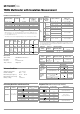
Influencing Quantities and Influence Error
1
With zero balancing
2
Power limiting: frequency x voltage max. 3 x 10
6
V x Hz
3
The accuracy specification is valid as of a display value of 10% and up to 100% of
the measuring range for both measuring modes with the TRMS converter in the A
AC and A (AC+DC) ranges.
5
Except for sinusoidal waveshape
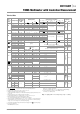
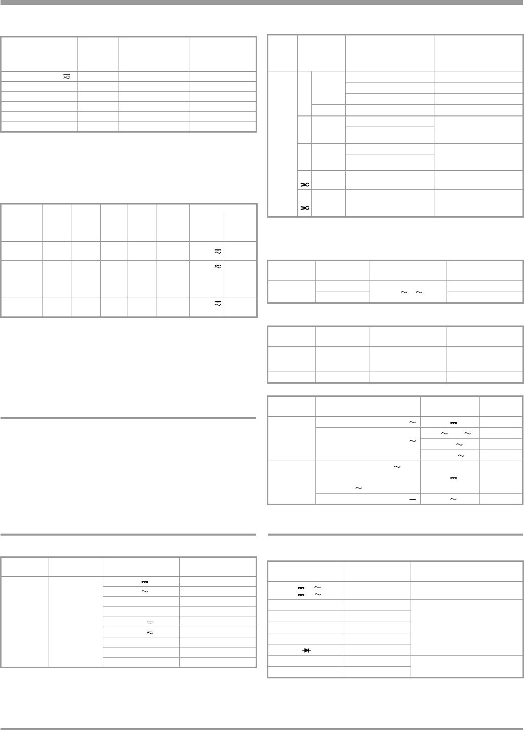
Response Time (after manual range selection)
Measuring Range Resolution
Nominal Voltage
U
ISO
2
V
Intrinsic Error
under Reference
Conditions
±
( % rdg + d)
300 mV ... 1000 V
Ri=1M
Ω
3 + 30 > 100 digits
5 ... 310.0 kΩ 0.1 kΩ
50, 100, 250, 500
3 + 5
0.280 ... 3.100 MΩ 1 kΩ
50, 100, 250, 500, 1000 V
3 + 5
02.80 ... 31.00 MΩ 10 kΩ
50, 100, 250, 500, 1000 V
5 + 5
028.0 ... 310.0 MΩ 100 kΩ
50, 100, 250, 500, 1000 V
5 + 5
0280 ... 3100 MΩ 1 MΩ
500, 1000 V
5 + 5
Measuring
Function
Nom.
Voltage
U
N
Open-
Circuit
Voltage
U
o
Nom.
Cur-
rent I
N
Short-
Circuit
Cur-
rent I
k
Acoustic
Signal
for
Overload Capacity
Value Time
U
interference
/
MΩ
@UISO
— —— —
U > 1000
V
1000 V Cont.
MΩ
@UISO
50,
100,
250,
500 V
Max.
1.1x U
Iso
1.0 mA < 1.2
mA
U > 1000
V
1000 V 10 s
MΩ
@UISO
1000 V Max.
1.1x U
Iso
0.5 mA < 1.2
mA
U > 1000
V
1000 V 10 s
Influencing
Quantity
Sphere of
Influence
Measured Quantity /
Measuring Range
1
Influence Error
(...% rdg. + ... d) / 10 K
Temperature
0 °C ... +21° C
and
+25° C ... +40° C
V 0.2 + 5
V 0.4 + 5
300 Ω ... 3 MΩ 0.5 + 5
30 MΩ 1 + 5
mA/A 0.5 + 5
mA/A 0.8 + 5
30 nF ... 300 μF1 + 5
Hz 0.2 + 5
°C/°F (Pt100/Pt1000) 0.5 + 5
Influ-
encing
Qty.
Measured
Quantity /
Measuring
Range
Sphere of Influence
Intrinsic error
3
±( ... % rdg. + ... d)
Fre-
quency
V
AC
2
300 mV
...
300 V
> 15 Hz ... 45 Hz 2 + 5 > 300 digits
> 65 Hz ... 2 kHz 2 + 5 > 300 digits
> 2 kHz ... 10 kHz 3 + 5 > 300 digits
1000 V > 65 Hz ... 5 kHz 3 + 5 > 60 digits
A
AC
300 μA
...
10 A
> 15 Hz ... 45 Hz
3 + 10 > 300 digits
> 65 Hz ... 10 kHz
A
AC
+DC
300 μA
...
10 A
> 15 Hz ... 45 Hz
3 + 30 > 300 digits
> 65 Hz ... 10 kHz
A
AC
300 mV /
3 V / 30 V
2
> 65 Hz ... 10 kHz 3 + 5 > 300 digits
A
AC
30 mA /
300 mA
3 A
> 65 Hz ... 10 kHz 3 + 30 > 300 digits
Influencing
Quantity
Sphere of
Influence
Measured Quantity /
Measuring Range
Influence Error
5
Crest factor CF
1 ... 3
V, A
± 1% rdg.
> 3 ... 5 ± 3% rdg.
Influencing
Quantity
Sphere of
Influence
Measured Quantity Influence Error
Relative
Humidity
75%,
3 days,
instrument off
V, A, Ω, F, Hz, °C1 x intrinsic error
Battery voltage 1.8 to 3.6 V ditto Included in intrinsic error
Influencing
Quantity
Sphere of Influence
Measured Qty. /
Measuring Range
Damping
Common Mode
Interference
Voltage
Interference quantity max. 1000 V V > 120 dB
Interference quantity max. 1000 V
50 Hz ... 60 Hz, sine
3 V , 30 V > 80 dB
300 V > 70 dB
1000 V > 60 dB
Series Mode
Interference
Voltage
Interference quantity: V ,
respective nominal value of the
measuring range,
max. 1000 V , 50 Hz ... 60 Hz sine
V> 50dB
Interference quantity max. 1000 V V > 110 dB
Measured Quantity /
Measuring Range
Response Time,
Digital Display
Jump Function
of the Measured Quantity
V, V
A, A
1.5 s
From 0 to 80%
of upper range limit value
300 Ω ... 3 MΩ 2s
From ∞ to 50%
of upper range limit value
30 MΩ,
MΩ
@U
ISO
Max. 5 s
Continuity < 50 ms
°C (Pt 100) Max. 3 s
1.5 s
30 nF ... 300 μFMax. 5s
From 0 to 50%
of upper range limit value
>10 Hz 1.5 s