
User Manual

6 GMC-I Messtechnik GmbH
If the symbol is included in the description of the surge pro-
tection device, the manufacturer’s instructions must be observed
for the respective device type.
The actual measurement is performed as follows:
➭ Select measurement of surge protection devices with the
R
ISO/USPD key, and select the desired sub-function with the
FUNC key (see also description above). Example:
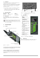
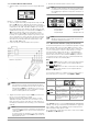
Figure 3.11: Surge Protection Device Measurement Menu,
DC Function
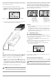
➭ Connect the test probes to the surge protection device in ac-
cordance with the manufacturer’s instructions.
Figure 3.12: Connection Example
Note
If a voltage of greater than about 10 V is present at the measured
surge protection device, its value is displayed and the START key is
disabled (see section 3.3.1 on page 4). Eliminate the source of
interference voltage before restarting the measurement.
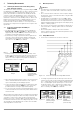
➭ Trigger measurement by pressing the START key. Release the
START key as soon as measurement is started. Rising current
at the surge protection device is displayed by means of a bar
graph. At the same time, the measuring voltage value appears
at the display in the U
IN field. Measurement is ended automat-
ically.
➭ Read voltage measured at the milliampere point.
Note
The device under test may not be disconnected from the
test instrument as long as the “!” warning symbol is lit up.
After insulation measurement has been completed, any remaining
residual voltage is displayed as UIN, which may result from cable
capacitance. Contact to the device under test must be main-
tained for as long as the capacitive DUT is being discharged via
the test instrument’s internal resistor. The falling voltage value can
be observed directly at the UIN display. Do not disconnect the
DUT until voltage U
IN is less than 25 V!
Comments
• Before measuring surge protection devices, disconnect them
from the installation.
• It’s advisable to study the circuit before performing measure-
ment. Surge protection devices are currently equipped with
integrated interference suppression filters and the like, which
may influence measurement results.
3.4 Further Device Functions
Select Language, Query Firmware Version
Before selecting a language or querying the firmware version, dis-
connect both test probes from the device under test / measuring
circuit and switch the test instrument off.
➭ Press and hold the R
ISO/USPD key while switching the test in-
strument on.
The firmware version and other service information appears at the
display, as well as the language selection menu.
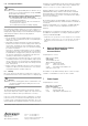
➭ Select the desired language with the corresponding key
(EN = English, CZ = Czech).
Figure 3.15: Language Selection Menu
The instrument is switched back to normal operation after a lan-
guage has been selected.
Measuring Point Illumination with White LED
The LED can be switched on and off by briefly pressing the START
key.
Note
No voltage may be applied to the test probes.
!
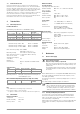
Figure 3.13: Sample Results
for the USPD
Measurement
(discharging is
active: residual
voltage = 144 V)
Figure 3.14: Further Sample
Results for the
U
SPD Measure-
ment (DUT is fully
discharged: resid-
ual voltage = 0 V)