
Operation Manual
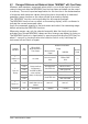
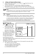
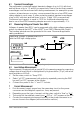
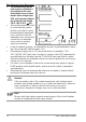

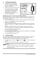
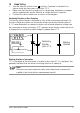
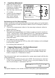
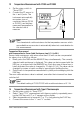
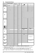
Table Of Contents
- 1 Safety Features and Precautions
- 2 Initial Start-Up
- 3 Selecting Measuring Functions and Measuring Ranges
- 4 Display (LCD)
- 5 Measured Value Storage – DATA / MIN-MAX Key
- 6 Voltage and Frequency Measurement
- 7 Current Measurement
- 8 Resistance Measurement
- 9 Continuity Testing
- 10 Diode Testing
- 11 Capacitance Measurment
- 12 Frequency Measurement – Duty Cycle Measurement
- 13 Temperature Measurement with Pt100 and Pt1000
- 14 Temperature Measurement with Type K Thermocouple
- 15 Characteristic Values
- 16 Maintenance
- 17 Multimeter Messages
- 18 Repair and Replacement Parts Service Calibration Center* and Rental Instrument Service
- 19 Product Support
GMC-I Messtechnik GmbH 13
6.1 Transient Overvoltages
The multimeter is protected against transient voltages of up to 4 kV with front
and half times of up to 1.2 and 50 s respectively. Due to the fact that powerful
overvoltages must be reckoned with during measurement, for example in power
systems, at transformers or motors, we recommend the use of our KS30 mea-
suring adapter in such cases. It offers protection against transient overvoltages
of up to 6 kV with front and half times of up to 10 and 1000 s respectively.
Continuous load capacity is equal to 1200 V
eff
. Additional measuring error
due to use of the KS30 measuring adapter amounts to approximately –2%.
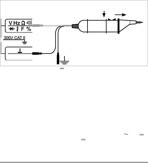
6.2 Measuring Voltages of Greater than 300 V
Voltages of greater than 300 V can be measured with a high-voltage measuring
probe, for example the HV3
1)
of the HV30
2)
from GMC-I Messtechnik GmbH.
The bonding terminal must be grounded in this case. Observe all applicable
safety precautions!
1)
HV3: 3 kV
2)
HV30: 30 kV for (DC) voltage only
6.3 Low-Voltage Measurement
The instrument is equipped with a special 30 mV measuring range for measuring
voltage drop at fuses which is distinguished by high resolution (10 V) with a low
input resistance of 50 k.
➭ Set the rotary switch to “Temp RTD”.
➭ Select “V DC” measurement with probe by repeatedly pressing the FUNC
key until “mV DC” appears at the display.
➭ Connect
the probe to the “” and “V” sockets.
7 Current Measurement
➭ First disconnect supply power from the measuring circuit or the power
consumer and discharge all capacitors, if any are present.
➭ Depending upon the type of current, set the rotary switch to “A ” or “A ”.
➭
The symbol for the selected current type, (DC) or ~ (AC), appears at the LCD.
➭ Connect the measuring instrument securely to the power consumer in se-
ries as shown in the diagram (without transition resistor).
black
black
red
x1000
x100
Measuring voltages of greater than 300 V
with the HV3 high-voltage probe