
Operation Manual
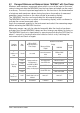
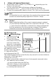
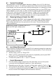
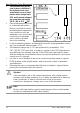

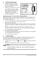
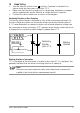
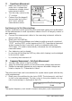
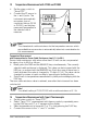
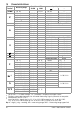
Table Of Contents
- 1 Safety Features and Precautions
- 2 Initial Start-Up
- 3 Selecting Measuring Functions and Measuring Ranges
- 4 Display (LCD)
- 5 Measured Value Storage – DATA / MIN-MAX Key
- 6 Voltage and Frequency Measurement
- 7 Current Measurement
- 8 Resistance Measurement
- 9 Continuity Testing
- 10 Diode Testing
- 11 Capacitance Measurment
- 12 Frequency Measurement – Duty Cycle Measurement
- 13 Temperature Measurement with Pt100 and Pt1000
- 14 Temperature Measurement with Type K Thermocouple
- 15 Characteristic Values
- 16 Maintenance
- 17 Multimeter Messages
- 18 Repair and Replacement Parts Service Calibration Center* and Rental Instrument Service
- 19 Product Support
GMC-I Messtechnik GmbH 15
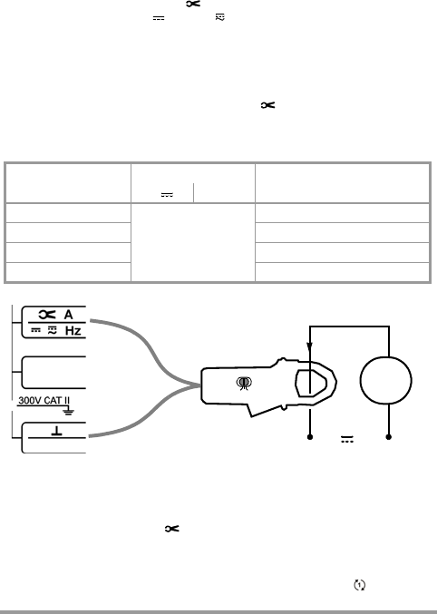
7.1 Current Measurement with Current (Clamp) Sensors with Voltage Output
If a current sensor is connected to the multimeter, all current values are displayed
correctly in consideration of the transformer ratio. This presupposes that the cur-
rent sensor is equipped with the required sensitivity, and that the
appropriate ratio is selected before measurement is performed.
➭ Turn the rotary switch to the position
.
➭ Select a current type,
A (DC) , A
( ) (AC+DC), Hz, RPM Upm1
or Upm2 (see below)
, by pressing the FUNC key.
➭ Simultaneously press the FUNC and the MAN/AUTO keys. The currently
selected transformation ratio is displayed. The transformer ratio can be
changed by pressing the MAN or the DATA key, or the currently selected value
can be retained by pressing the FUNC key.
➭ Connect the current (clamp) sensor to the and the jacks.
Please observe the specified operating conditions per IEC/EN 61010-2-32
regarding measurement category, etc. for the applied current sensor.
Additional error caused by the current sensor must be taken into consideration.
7.2 RPM Measurement at combustion engines
RPM is measured by acquiring pulses. The number of measurable pulses per
revolution varies depending upon the type of engine (2 or 4 stroke).
➭ Set the rotary switch to “ ”.
➭ Press the multifunction key (
FUNC
)
repeatedly until unit of measure
Upm1
(RPM measurement at 2 stroke engines: 1 pulse per revolution) or Upm2 (RPM
measurement at 4 stroke engines: 1 pulse for 2 revolutions)
is briefly displayed.
The measured value then appears, for example “244.3
Upm
”.
M
I(A)
V/~
* for short-circuited measuring cables: residual value 1 ...
70
d at zero point due to TRMS converter
Current sensor
transformer ratio
max. measuring range
Measuring ranges
available in the multimeter
A A~ *
1/ 1 V / A
depending on the applied
current sensor
0 ... 300.00 mA/3.000 A/30.00 A
1 / 10 V / A 0 ... 3.0000 A/30.000 A/300.00 A
1 / 100 V / A 0 ... 30.000 A/300.00 A/3.0000 kA
1 / 1000 V / A 0 ... 300.00 A/3.0000 kA/30.000 kA