
Operation Manual
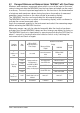
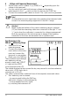
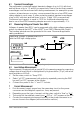
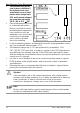

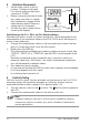
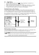
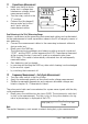
Table Of Contents
- 1 Safety Features and Precautions
- 2 Initial Start-Up
- 3 Selecting Measuring Functions and Measuring Ranges
- 4 Display (LCD)
- 5 Measured Value Storage – DATA / MIN-MAX Key
- 6 Voltage and Frequency Measurement
- 7 Current Measurement
- 8 Resistance Measurement
- 9 Continuity Testing
- 10 Diode Testing
- 11 Capacitance Measurment
- 12 Frequency Measurement – Duty Cycle Measurement
- 13 Temperature Measurement with Pt100 and Pt1000
- 14 Temperature Measurement with Type K Thermocouple
- 15 Characteristic Values
- 16 Maintenance
- 17 Multimeter Messages
- 18 Repair and Replacement Parts Service Calibration Center* and Rental Instrument Service
- 19 Product Support

16 GMC-I Messtechnik GmbH
8 Resistance Measurement
➭ Set the rotary switch to the
position. Overload is indicated
if no device under test has been
connected: “0.L M”.
➭ Before connecting the device under
test, make sure that it is voltage-
free. Interference voltages distort
measurement results! Perform a
voltage test first if required.
➭ Connect the device under test as
shown in the diagram.
Zero Balancing in the 30 , 300 and 3 kMeasuring Ranges
Resistance at cables, as well as contact resistances, can be eliminated for the
measurement of low-resistance values in the 30 , 300 and 3 k ranges by
means of zero balancing:
➭ Connect the measurement cables to the instrument and connect the free
ends to one another (short circuit the test probes).
➭ Briefly press the FUNC key.
The instrument acknowledges zero balancing with an acoustic signal, and
“00
.00 ”, “ 000.00 ” or “0.0000 k”and the ZERO symbol appear at the
LCD.
Resistance measured at the moment the key is pressed is used as a
reference value (max. 2000 digits). This value is automatically subtracted
from all subsequently measured values.
➭ Zero balancing can be cleared:
– by pressing and holding the FUNC key, after which clearing is acknowledged
by a twice repeated acoustic signal,
– by switching the instrument off.
9 Continuity Testing
With the “acoustic signal” function activated, and exclusively in the 0 to 310
measuring range, the instrument generates a continuous acoustic tone for
measured resistance within a range of 0 to approximately 2 .
➭ Turn the selector switch to the position. The and symbols appear at
the LCD.
➭ Connect the measurement cables to the device under test.
Note!
Continuity testing is very fast (< 50 ms) and is suitable for locating
connections with poor contact (e.g. due to vibration) in automotive
service applications.
R
x
Voltage Drop