
Operation Manual
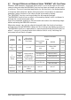
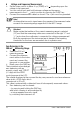
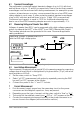
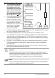

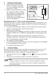
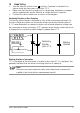
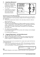
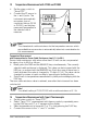
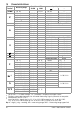
Table Of Contents
- 1 Safety Features and Precautions
- 2 Initial Start-Up
- 3 Selecting Measuring Functions and Measuring Ranges
- 4 Display (LCD)
- 5 Measured Value Storage – DATA / MIN-MAX Key
- 6 Voltage and Frequency Measurement
- 7 Current Measurement
- 8 Resistance Measurement
- 9 Continuity Testing
- 10 Diode Testing
- 11 Capacitance Measurment
- 12 Frequency Measurement – Duty Cycle Measurement
- 13 Temperature Measurement with Pt100 and Pt1000
- 14 Temperature Measurement with Type K Thermocouple
- 15 Characteristic Values
- 16 Maintenance
- 17 Multimeter Messages
- 18 Repair and Replacement Parts Service Calibration Center* and Rental Instrument Service
- 19 Product Support
18 GMC-I Messtechnik GmbH
11 Capacitance Measurment
➭ Make sure that the device
under test is voltage-free.
Interference voltages distort
measurement results!
➭ Turn the rotary switch to the
“F” position.
➭ Connect the (discharged!)
device under test to the
and V jacks with the
measurement cables.
Zero Balancing in the 30 nF Measuring Range
Intrinsic capacitance at the measuring instrument and cables can be eliminated
for the measurement of small capacitance values in the 30 nF range by means of
zero balancing:
➭ Connect the measurement cables to the measuring instrument without a
device under test.
➭ Briefly press the FUNC key.
The instrument acknowledges zero balancing with an acoustic signal and
“00
.00 ” and the ZERO symbol appear at the LCD. Capacitance measured
at the moment the key is pressed is used as a reference value (max.
2000 digits). This value is automatically subtracted from all subsequently
measured values.
➭ Zero balancing can be cleared:
– by pressing and holding the FUNC key, after which clearing is acknowledged
by an acoustic signal,
– by switching the instrument off.
12 Frequency Measurement – Duty Cycle Measurement
➭ Turn the rotary switch to the Hz position.
➭ Apply the measured quantity as described under voltage measurement.
➭ Smallest measurable frequencies and maximum allowable voltages are
listed in chapter 15, “Characteristic Values”.
The pulse-period ratio can be ascertained for square-wave signals with the duty
cycle measurement.
➭ Briefly press the multifunction key twice (FUNC). The instrument is switched
to duty cycle measurement. The duty cycle, i.e. the pulse duration of a sig-
nal as a percentage, is displayed at the LCD.
Note
The applied frequency must remain constant during duty cycle measurement.
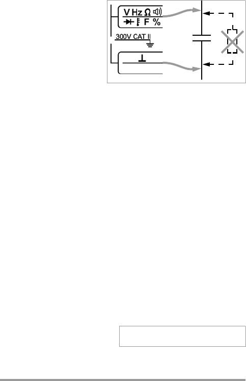
+
–
Duty Cycle (%) = ——————— • 100
Pulse Duration
Period