
Operation Manual

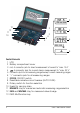
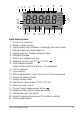
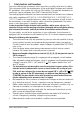
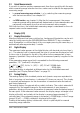
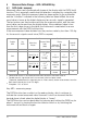
Table Of Contents
- 1 Safety Features and Precautions
- 2 Initial Start-Up
- 3 Selecting Measuring Functions and Measuring Ranges
- 4 Display (LCD)
- 5 Measured Value Storage – DATA / MIN-MAX Key
- 6 Voltage and Frequency Measurement
- 7 Current Measurement
- 8 Resistance Measurement
- 9 Continuity Testing
- 10 Diode Testing
- 11 Capacitance Measurment
- 12 Frequency Measurement – Duty Cycle Measurement
- 13 Temperature Measurement with Pt100 and Pt1000
- 14 Temperature Measurement with Type K Thermocouple
- 15 Characteristic Values
- 16 Maintenance
- 17 Multimeter Messages
- 18 Repair and Replacement Parts Service Calibration Center* and Rental Instrument Service
- 19 Product Support
2 GMC-I Messtechnik GmbH
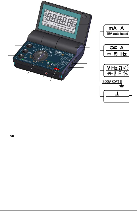
Control Elements
1LCD
2 Battery compartment cover
3 mA, A connector jack for direct measurement of current to “max. 10 A”
4 A connector jack for current clamp measurement to “max. 30 V”
5 Connector jack for all measuring ranges except current measuring ranges
6“”connector jack for all measuring ranges
7 OFF/ON: ON/OFF switch
8 Resettable miniature circuit breaker (AUTO FUSE)
9 Rotary switch for function selection
10 Eyelet for carrying strap
11
MAN/AUTO
: Key for manual and automatic measuring range selection
12 DATA and MIN/MAX: Key for measured value storage
13 FUNC: Multifunction key
1
2
7
9
10
12
13
11
8
3
4
5
6
3
4
5
6