
Operation Manual
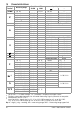
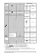

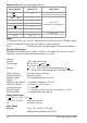
Table Of Contents
- 1 Safety Features and Precautions
- 2 Initial Start-Up
- 3 Selecting Measuring Functions and Measuring Ranges
- 4 Display (LCD)
- 5 Measured Value Storage – DATA / MIN-MAX Key
- 6 Voltage and Frequency Measurement
- 7 Current Measurement
- 8 Resistance Measurement
- 9 Continuity Testing
- 10 Diode Testing
- 11 Capacitance Measurment
- 12 Frequency Measurement – Duty Cycle Measurement
- 13 Temperature Measurement with Pt100 and Pt1000
- 14 Temperature Measurement with Type K Thermocouple
- 15 Characteristic Values
- 16 Maintenance
- 17 Multimeter Messages
- 18 Repair and Replacement Parts Service Calibration Center* and Rental Instrument Service
- 19 Product Support
GMC-I Messtechnik GmbH 21
1)
At 0 ° to + 40 C
2)
Values of less than 2 mV are suppressed in the 300 mV range
15 (20) 45 ... 65 Hz 10 kHz sine, see page 22 for influences.
3)
After measurement with 10 A: at least 10 minute cool-down period
4)
If “zero balancing” function is active, ZERO appears at display.
5)
Plus sensor error
6)
Specified intrinsic uncertainty valid for 3
to
100% of the AC measuring ranges
with short-circuited test probes: residual value 1 to 30 d at zero point due to TRMS converter
7)
Intrinsic error values valid as of 10 digits
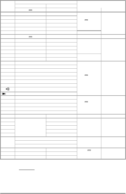
Measuring
Range
Intrinsic Uncertainty under Reference Conditions
Overload Capacity
1)
( % rdg. + d) ( % rdg. + d)
~
2) 6)
Value Duration
30 mV 1 + 5 —
600 V
(DC)
~ (AC)
eff sine
continuous
300 mV 0.2 + 5
4) 7
1+30
3 V 0.2+3 0.5+30
30 V 0.2+3 0.5+30
300 V 0.2+3 0.5+30
600 V 0.2 + 3 0.5 + 30 600 V CAT I
~
2) 6
300 A 0.5+5 1.5+30
0.36 A
dauernd
3 mA 0.5+5 1.5+30
30 mA 0.5+5 1.5+30
300 mA 0.5+5 1.5+30
3 A 0.7+5 1.5+30
10 A
3
10 A 0.7+5 1.5+30
30 1+5
300 V
(DC)
~ (AC)
eff
Sinus
max. 10 s
300 0.2+5
4)
3k 0.2+5
4)
[to 1 k: (0.2 + 9 D)]
30 k 0.2+5
300 k 0.2+5
3M 0.2+5
30 M 2+10
3+5
5.1 V 0.5 + 3
30 nF 1 + 6
4)
300 V
(DC)
~ (AC)
eff
sine
max. 10 s
300 nF 1 + 6
3 F 1 + 6
30 F 1 + 6
300 F 1 + 6
Max. Measuring Voltage
300.00 Hz
0.1 + 5
(sinusoidal input
voltage > 2 ... 5)
300 V
300 V max. 10 s
3.0000 kHz 300 V
30 kHz 300 V
300 kHz 100 V
1000 kHz 30
%
0.1% MR 8 d
300 V max. 10 s0.1% MR/kHz 8 d
0.1% MR/kHz 8 d
Pt 100 – 200.0 ... +850.0 C 0.5% + 15
5)
300 V (DC) /
~(AC)
eff sine
max. 10 sPt1000 – 150.0 ... + 850.0 C 0.5% + 15
5)
K / NiCr-Ni – 250.0 ... +1372.0 C 1% + 5 K
5)