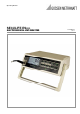
Operating Manual SECULIFE ESPRO ELECTROSURGICAL UNIT ANALYZER 3-349-624-03 1/5.
SECULIFE ESPRO Contents WARNINGS, CAUTIONS, NOTICES ....................................................................................... 4 DESCRIPTION ......................................................................................................................... 9 TYPICAL TEST SETUP.......................................................................................................... 12 OVERVIEW ................................................................................................
SECULIFE ESPRO WARNING - USERS The SECULIFE ESPRO Analyzer is for use by skilled technical personnel only. WARNING - USE The SECULIFE ESPRO Analyzer is intended for testing only and he should never be used in diagnostics, treatment or any other capacity where they would come in contact with a patient. WARNING - MODIFICATIONS The SECULIFE ESPRO Analyzer is intended for use within the published specifications.
SECULIFE ESPRO CAUTION - SERVICE The SECULIFE ESPRO Analyzer is intended to be serviced only by authorized service personnel. Troubleshooting and service procedures should only be performed by qualified technical personnel. CAUTION - ENVIRONMENT The SECULIFE ESPRO Analyzer is intended to function between 15 and 30 °C. Exposure to temperatures outside this range can adversely affect the performance of the Analyzer. CAUTION - CLEANING Do not immerse.
SECULIFE ESPRO 6 GMC-I Messtechnik GmbH
SECULIFE ESPRO NOTICE – SYMBOLS Symbol Description Caution (Consult Manual for Further Information) RF Current Transformer Per European Council Directive 2002/95/EC, do not dispose of this product as unsorted municipal waste.
SECULIFE ESPRO NOTICE – DISCLAIMER USER ASSUMES FULL RESPONISIBILITY FOR UNAUTHORIZED EQUIPMENT MODIFICATIONS OR APPLICATION OF EQUIPMENT OUTSIDE OF THE PUBLISHED INTENDED USE AND SPECIFICATIONS. SUCH MODIFICATIONS OR APPLICATIONS MAY RESULT IN EQUIPMENT DAMAGE OR PERSONAL INJURY. NOTICE – DISCLAIMER GMC-I MESSTECHNIK GMBH RESERVES THE RIGHT TO MAKE CHANGES TO ITS PRODUCTS OR SPECIFICATIONS AT ANY TIME, WITHOUT NOTICE, IN ORDER TO IMPROVE THE DESIGN OR PERFORMANCE AND TO SUPPLY THE BEST POSSIBLE PRODUCT.
SECULIFE ESPRO Gossen Metrawatt SECULIFE ESpro ELECTROSURGICAL UNIT ANALYZER The SECULIFE ESPRO Electrosurgical Unit Analyzer is a high-accuracy True RMS RF Voltmeter designed to be used in the routine performance verification of Electrosurgical Generators. The SECULIFE ESPRO offers a higher degree of accuracy than previously attainable with conventional Electrosurgical Unit Analyzer designs.
SECULIFE ESPRO The following are highlights of some of the main features: TRUE RMS READINGS USING DFA™ TECHNOLOGY INDUSTRY STANDARD CURRENT SENSING TECHNOLOGY MV, MV PEAK, MA, CREST FACTOR AND POWER (WATTAGE) RANGES LARGE GRAPHICS DISPLAY WITH CURSOR SELECTION OF OPTIONS AND SETUP OF PARAMETERS 1% OF READING MEASUREMENT ACCURACY DIGITAL DATA OUTPUT VIA USB AND RS232 PC BASED INTERFACE AND DATA CAPTURE PROGRAM DIGITAL CALIBRATION – NO POTS TO TURN SELECTABLE DISPLAY OPTIONS DISPLAY CONT
SECULIFE ESPRO CURRENT TRANSFORMERS: Z697B Z697A PEARSON ELECTRONICS MODEL 411 0.
SECULIFE ESPRO TYPICAL TEST SETUP Unlike all conventional ESU Analyzers with lesser degrees of accuracy, the SECULIFE ESPRO utilizes an external Current Transformer and external precision load resistors (values to be determined by the manufacturer’s suggested test load for the generator you are testing or servicing) for typical Electrosurgical Generator testing.
SECULIFE ESPRO OVERVIEW This section looks at the layout of the SECULIFE ESPRO and gives descriptions of the elements that are present.
SECULIFE ESPRO MAIN SCREENS – There are 7 main screens, 5 Display Screens which have 1, 2, 3, 4 and 5 display zones respectively, a Measurement List Screen which shows available measurements and the Quick Config Screen which displays the current hardware configuration. In the Display Screens, each Display Zone can be customized to show the desired parameter from the following options: 14 Parameter Abbreviation Description mV RMS mV This is the mV measured directly from the RF donut.
SECULIFE ESPRO Ton Toff Tcyc Diagram 1 The available screens can be toggled through using mV mA Watts CF mVcyc mAcyc Wcyc .
SECULIFE ESPRO Five Display Zone Screen with mV, Watts, mA and mV Peak and CF parameters selected Measurement List Screen: Measured Parameters Parameter mV RMS mA RMS Watts RMS mV Peak mV Peak - to - Peak mV Peak / Peak - to - Peak mV Positive Peak Crest Factor Time Pulse – On Time - Pulse Off Time - Total Cycle % Duty Cycle mV Pulse mA Pulse Watts Pulse 16 Abbreviation mV mA Watts mV Pk mV P-P Pk/P-P mV Pk+ CF Ton Toff Tcyc %Duty mV cyc mA cyc Wcyc GMC-I Messtechnik GmbH
SECULIFE ESPRO Quick Config Screen: Donut Atten 0.1 : 1 1 :1 Input Range 100 mV 1000 mV Auto Load Resistance 0 – 6,500.0 ohms Input Mode (ESU-2050P Only) NOTE: Load Resistance can be Adjustable or Selected from the table of available resistor combinations. (See Load Table for more information).
SECULIFE ESPRO DISPLAY PARAMETERS – There are five options of parameters that can be selected for each Display Zone on the Main Screens. This allows users to custom configure the displays to best suit their needs. Use to highlight the Display Zone to change and then to sequence through the available parameters. NOTE: To save a custom configuration, see Power Up Settings section. SYSTEM CONFIGURATION SCREEN – The SYSTEM SETUP MODE allows the user to adjust the configuration of the unit.
SECULIFE ESPRO The following is a breakdown of the parameters available in the configuration of the unit and their available options: System Setup Configuration Parameter Description Range Donut Atten Selects the RF Current Transformer Attenuation in Volts : Amp for the RF Donut being used. Default = 0.1 : 1 0.1 : 1 1:1 Volts : Amps Input Zero Zeros the input circuitry based on donut being used. Each donut can have a slightly different zero offset.
SECULIFE ESPRO System Setup Configuration Parameter Slow Averaging Medium Averaging Fast Averaging Averaging Window Load Set 1 Load Set 2 Load Set 3 Load Set 4 20 Description Sets the number of mV RMS readings that are averaged when the Display Averaging parameter is set to Slow. A higher number will cause the display to update slower, but will give a more stable reading Default = 150 Sets the number of mV RMS readings that are averaged when the Display Averaging parameter is set to Medium.
SECULIFE ESPRO System Setup Configuration Parameter Load Set 5 Load Set 6 Load Set 7 Load Set 8 Load Set 9 Load Set 10 Description Assigns a resistance value for Set 5 from a combination of the available loads as determined by the Load Resistance Values set in the Factory Setup. (See Custom Load Sets for more information.) Default = None Selected Assigns a resistance value for Set 6 from a combination of the available loads as determined by the Load Resistance Values set in the Factory Setup.
SECULIFE ESPRO INPUT ZERO – The Input Zero offset can be slightly different between RF donuts. This parameter accesses an auto-zeroing function that eliminates this offset. Independent settings are saved for the 0.1:1 RF donut and 1:1 RF donut. The user can switch between the two donut types without having to rezero the input. The input needs to be zeroed only when a new donut is introduced. INPUT RANGE – The input range can be scaled to accommodate the signal that is being measured.
SECULIFE ESPRO CUSTOM LOAD SETS. To simplify the selection of commonly used load configurations, 10 custom resistor sets are available. Each resistor set can consist of any combination of the available calibrated loads. The number of loads and load calibration is performed in the Factory Setup Screen.
SECULIFE ESPRO LOAD TABLE – Up to twelve Load Resistance Values (each with a range from 0.0 to 6,500.0 ohms) may be set in the FACTORY SETUP Configuration. These values are used in combination with the Custom Load Sets to determine the Load Configuration Table. These options are available if the Load Selection parameter is set to “Table”. The settings will be the individual calibrated loads followed by the Load Sets.
SECULIFE ESPRO LOAD CALIBRATION SCREEN – The LOAD SETUP MODE allows the user to adjust the calibration of the loads. The Load Setup Screen can be entered using the key while in the SYSTEM SETUP MODE. The parameters can be changed by using to highlight the line and to toggle the available options. The Load Setup Screen can be exited using the key.
SECULIFE ESPRO The following is a breakdown of the parameters available in the LOAD SETUP MODE and their available options: Load Setup Configuration Parameter Number Of Loads Load 1 Load 2 Load 3 Load 4 Load 5 Load 6 Load 7 Load 8 Load 9 Load 10 Load 11 Load 12 26 Description Sets the number of load resistors present in the system. This determines the maximum combination of resistors available when the Load Selection is set to Table. Calibrates the Load 1 Resistance Value.
SECULIFE ESPRO FACTORY SETUP SCREEN – The FACTORY SETUP MODE allows for the configuration of system parameters that the standard user should not access. This setup allows for Calibration of the system. The Factory Setup Screen can be entered by pressing and holding the key for five seconds while in the SYSTEM SETUP MODE. This will open an Access Code Window. Use to change the displayed code to 135. Then is used to access the FACTORY SETUP MODE.
SECULIFE ESPRO Typical Setup Screen The following is a breakdown of the parameters available in the configuration of the unit and their available options: Factory Setup Configuration Parameter Description Range Input Range Used to select the input range that is to be calibrated. Donut Attenuation Selects the Attenuation in Volts : Amp for the RF Current Transformer being used. Each setting has an independent gain setting. 100 mV 1000 mV 0.
SECULIFE ESPRO LINE POWER – A Kycon 3 pos locking connector is provided for the 6 VDC Universal Power Supply input. The Universal Power Supply takes a Standard Power Adapter Cable with Small Standard Product Plug and Required International Connector (See Options Below).
SECULIFE ESPRO SERIAL COMMUNICATION – There is a serial port on the rear panel. The RS-232 Port is used for Firmware upgrades USB COMMUNICATION – There is a USB port on the rear panel. The USB Port is used to interface with a PC. POWER SWITCH - The main power switch for the Analyzer is located on the left side on the rear panel.
SECULIFE ESPRO KEYS Ten tactile-touch keys are provided for system operation: – In the Main Screen, these keys will scroll through the available display screens. In the GRAPH MODE, these keys will scroll through the horizontal zoom level for the graph. – In the Main Screen, these keys will toggle through the available Display Zones. In the SETUP MODE, these keys will scroll through the available parameters. In the GRAPH MODE, these keys will select the waveform to be displayed.
SECULIFE ESPRO – In the SETUP MODE, this key is used to exit and return to the previously viewed Main Screen. This will also save any changes to the internal EEPROM memory so they will be retained even with the power turned off. In the GRAPH MODE, this key is used to exit and return to the previously viewed Main Screen. In the SAVE MODE, this key is used to exit without saving. – In the Main Screen, this key is used to enter the GRAPH MODE. In the GRAPH MODE, this key is used to enter the SAVE MODE.
SECULIFE ESPRO POWER UP SETTINGS The SECULIFE ESPRO allows the user to customize the settings that the unit will have on Power Up. The “Power up with” parameter in the System Setup Menu allows for the selection of either Default or Custom selections. Use to enter the SETUP MODE. Use Use to change the parameters to Default, Custom or Set Current as Custom. The Setup screen can be exited using the to select the “Power up with” parameter. key.
SECULIFE ESPRO Set Current as Custom This choice is provided to create the set of custom startup screen parameters. The user simply configures each of the five display screens to show the desired parameters in each Display Zone, selects this option and presses RETURN. The current configuration is then saved as the Custom Power Up values and will be used when the “Power up with” parameter is set to Custom.
SECULIFE ESPRO GRAPH MODE The GRAPH MODE allows the user to view the measured waveform in the display. The horizontal axis can be zoomed in to display higher frequency waveform components. The vertical axis is auto-scaling and cannot be adjusted. Any of the stored waveforms can be graphed. Additionally, if the unit is placed in the HOLD MODE, the user can adjust which portion of the waveform is being displayed.
SECULIFE ESPRO Location Indicator Use to select a specific portion of the waveform buffer to be graphed. The Location Indicator is a small square that moves along the bottom of the Graph Screen to indicate where the current viewing window portion of the waveform is from within the overall data set. Location Indicator Zooming Use to zoom the graph in and out. The Zoom Indicator is a bar that moves along the left side of the Graph Screen to indicate the Zoom level shown in the current viewing window.
SECULIFE ESPRO Saving To save the displayed waveform, use Use to enter the SAVE MODE. to select the desired storage location, then to save the waveform, or can be pressed to cancel the save function. Once the save is complete, the newly saved waveform will be displayed.
SECULIFE ESPRO ERROR MESSAGES Several error messages are provided to indicate invalid operating conditions. Any values that are over range will be displayed as dashes. Watts Calculation out of range Peak Voltage Input Out of range When the input voltage rises above the range that is measurable by the system, the “WARNING Input Overload” message will be shown.
SECULIFE ESPRO DFA™ TECHNOLOGY DFA™ Digital Fast Acquisition Technology is a revolutionary new method of measuring ESU generator output power. A high-speed analog to digital converter is used to digitize the high frequency, high power output of the ESU generator. An RF Current Transformer is used to convert the current signal to a voltage signal, which is read by the a/d converter. By digitizing the signal a more accurate, frequency independent measurement can be made.
SECULIFE ESPRO COMMUNICATION PROTOCOL The communication protocol provides a means to completely configure and use the SECULIFE ESPRO from a PC. All of the functions available through the front panel can be performed through the communication ports. All of the measurements made by the SECULIFE ESPRO are accessible as well. This provides for hands free or automated operation of the SECULIFE ESPRO. Communication Ports The SECULIFE ESPRO has two communication ports. Both ports use the same command format.
SECULIFE ESPRO Not all commands require the complexity of the full command path. For example, the Status? command doesn’t have a Node or Subnode. Some commands allow for reading and writing data and some commands are Read Only. To indicate a read function, a question mark (?) is placed at the end of the command path. For example, a write command to change the load resistance to 100.5 ohms would be “CONFigure:LOAD:VALue 100.5”, where indicates a carriage-return.
SECULIFE ESPRO CONFigure Subsystem This group allows the user to setup the display and operational settings for the unit.
SECULIFE ESPRO SYSTem Subsystem This group allows the user to setup the startup mode for the unit, as well as directly control the unit, as if pressing the keys on the front panel. KEYWORD PARAMETER FORM SYSTem: POWer CONtrast KEY DEFaults | CUStom | SETCurrent < numeric_value > DUP | DDN | SUP | SDN | VUP | VDN | SETup | RETurn | GSAVe | HOLD VER? COMMENTS Numbers 1-20 Read only READ Subsystem This group allows the user to get measurements from the unit.
SECULIFE ESPRO SECULIFE ESPRO Communication Command Summary Keywords CONFigure Nodes DISPlay Subnodes SxZy nn SCReen HOLD LOAD AVERaging ON,OFF MODE VALue SETn xxxx Values x is the Screen # (1-5) and y is the Zone # (1-5).
SECULIFE ESPRO SECULIFE ESPRO Communication Command Summary Keywords READ Nodes MVrms? Subnodes Values Returns: mV RMS [read only] MArms? Returns: mA RMS [read only] WArms? Returns: Watts RMS [read only] MVPeak? Returns: mV Peak [read only] MVPP? Returns: mV Peak to Peak [read only] MVP-PP? Returns: mV Peak/Peak to Peak [read only] MVPK+? Returns: mV Positive Peak [read only] CF? Returns: Crest Factor [read only] TON? Returns: Time - Pulse On [read only] TOFF? Returns: Time - Pulse Off
SECULIFE ESPRO LIMITED WARRANTY WARRANTY: GMC-I MESSTECHNIK GMBH WARRANTS ITS NEW PRODUCTS TO BE FREE FROM DEFECTS IN MATERIALS AND WORKMANSHIP UNDER THE SERVICE FOR WHICH THEY ARE INTENDED. THIS WARRANTY IS EFFECTIVE FOR TWELVE MONTHS FROM THE DATE OF SHIPMENT. EXCLUSIONS: THIS WARRANTY IS IN LIEU OF ANY OTHER WARRANTY EXPRESSED OR IMPLIED, INCLUDING, BUT NOT LIMITED TO ANY IMPLIED WARRANTY OF MERCHANTABILITY OR FITNESS FOR A PARTICULAR PURPOSE.
SECULIFE ESPRO SPECIFICATIONS 100 mV INPUT RANGE Voltage (RMS) 20 – 70.00 mV RMS Input Resolution 0.01 mV RMS Voltage (Peak, Peak - to - Peak) 100.0 mV Resolution 0.01 mV Frequency 10 kHz – 10 MHz 0.5 mV, < 50 mV, up to 1 MHz 1.0 mV, < 50 mV, 1 to 10 MHz 1% reading, > 50 mV, up to 1 MHz 3% reading, > 50 mV, 1 to 5 MHz 12% reading, > 50 mV, 5 to 10 MHz Accuracy 3.3 V p-p Internally Protected Maximum Input Voltage CALCULATED RANGES Current (with 0.1:1 CT) 700.0 mA RMS Resolution 0.
SECULIFE ESPRO 1000 mV INPUT RANGE Voltage (RMS) 2.0 – 700.0 mV RMS Input Resolution 0.1 mV RMS Voltage (Peak, Peak - to - Peak) 1000.0 mV Resolution 0.1 mV Frequency 10 kHz – 10 MHz 0.5 mV, < 50 mV 1% reading, > 50 mV, up to 1 MHz 3% reading, > 50 mV, 1 to 10 MHz 3.3 V p-p Internally Protected Accuracy Maximum Input Voltage CALCULATED RANGES Current (with 0.1:1 CT) 7000 mA RMS Resolution 1 mA Current (with 1:1 CT) 700.0 mA RMS Resolution 0.1 mA mV Peak / Peak - to - Peak 0.0 to 1.
SECULIFE ESPRO TIMING MEASUREMENTS FOR Ton, Toff, Tcyc and % Duty Cycle Resolution 0.1 ms Accuracy + 0.2 ms DISPLAY LCD Graphical 128 X 64 Pixels SETUP MEMORY EEPROM, All Parameters MEMORY RETENTION 10 Years w/o Power OPERATING RANGE 15 to 30 Degrees C STORAGE RANGE -40 to 60 Degrees C CONSTRUCTION SIZE WEIGHT CONNECTIONS POWER SUPPLY ADAPTER POWER CONSUMPTION DATA STORAGE (Internal) GMC-I Messtechnik GmbH Enclosure – ABS Plastic Face – Lexan, Back Printed 3.4 x 9.1 x 8.0 inches 86.
SECULIFE ESPRO NOTES 50 GMC-I Messtechnik GmbH
Product Support If required please contact: GMC-I Messtechnik GmbH Product Support Hotline Phone +49 911 8602-0 Fax +49 911 8602-709 E-Mail support@gossenmetrawatt.com Service Center Repair and Replacement Parts Service Calibration Center * and Rental Instrument Service When you need service, please contact: GMC-I Service GmbH Service Center Thomas-Mann-Strasse 20 90471 Nürnberg • Germany Phone +49 911 817718-0 Fax +49 911 817718-253 E-Mail service@gossenmetrawatt.com www.gmci-service.