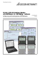
Operating Instructions SI 232-II, BD 232 Interface Adapter with METRAwin 10 / METRA Software for Measuring and Recording Systems with Multimeters 3-348-636-02 6/5.
1 2 3 Contents Page Introduction .............................................................................................................. 3 System Requirements .............................................................................................. 3 Multimeter, Adapter and METRAwin 10 Operating Modes ....................................... 4 3.1 3.2 3.3 3.4 3.5 3.6 3.7 General Information ............................................................................................
1 Introduction Interface Adapter Whereas interface adapter BD232 allows for online transmission of measured values from multimeter to PC, memory adapter SI232/-II is additionally capable of saving multimeter data on-site without a PC. The values thus stored to memory can subsequently be transmitted to a PC. PC-Analysis Software METRAwin 10 is a high-performance analysis software for use with WINDOWS.
3 Multimeter, Adapter and METRAwin 10 Operating Modes 3.1 General Information • The address for the adapter and its corresponding multimeter must be identical. • The baud rates for the adapter and the multimeter must also be the same. • The multimeter’s sampling rate should be faster than the speed at which data are requested by the memory adapter or METRAwin 10 software. 3.
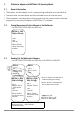
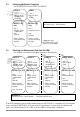
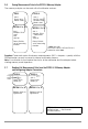
3.4 Configuring Multimeter Parameters – for all METRAHit 2x with SI232-II or BD232 PC 3.5 SI232-II BD232 Adr: 1 Bd-PC: 9600 Bd-MM: 8192 Mode: pc Adr: 2 Bd-PC 9600 fixed METRAHit 2x only METRAHit 2x only Adr: 1 Adapter: SI232 * store/online rate: send off Adr: 2 Adapter: BD232 Rotary Switch: set to measuring function Rotary Switch: set to measuring function METRAwin 10 Set/Device type..., Set/Channels ... rate: send off * online only with METRAHit 28S or 29S, otherwise select store.
3.6 Saving Measurement Data to the SI232/-II Memory Adapter The memory adapter can be used with all multimeter versions. SI232 SI232-II Adr: 1 Baud: 9600 Mode: store Adr: 2 Bd-PC: 9600 Bd-MM: 8192 Mode: store METRAHit 1x, 2x METRAHit 1x, 2x Adr: 1 Adapter: SI232 store rate: send on Adr: 2 Adapter: SI232 * store/online rate: send on Rotary Switch: set to measuring function Rotary Switch: set to measuring function * online only with METRAHit 28S or 29S und SI232-II, otherwise select store.
4 Adapter Connection and Initial Start-Up 4.1 Connecting the Adapter The screw connections between the stacked adapters serve exclusively to secure the connections at the serial interface plug connectors. Disconnect each individual adapter prior to transport in order to prevent them from being damaged. ➭ Connect the 9-pin subminiature socket at the connector cable to a vacant COM port at the PC. ➭ Plug the other end of the cable into the left side of the first adapter.
➭ After selecting the “File/Measure” menu item, the recorded measurement values are transmitted to the PC and are displayed at the monitor in accordance with the display mode selected in the “Set” menu. 4.3 Initial Start-Up – BD232 Interface Adapter ➭ Set the multimeter to the data transmission mode before performing measurement by simultaneously pressing the DATA key and the ON key. ➭ Start the PC and METRAwin 10 software.
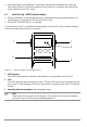
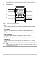
5 Operating Elements, Switching the Adapter ON and OFF, Replacing the Batteries 5.1 Keypad, Interface 1 3 DATA ON 21.978 mA 3 5 4 6 2 Figure 4.2 7 2 Memory Adapter Operating Elements 1 LCD Displays the respective menu item during manual operation of the memory adapter. 2 Connection between two adapters with fastening screws 3 RS232 Interface The RS232 data interface connects the adapters to one another, and to the PC.
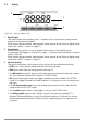
5.2 Display 3 1 2 Figure 4.3 1 2 3 Memory Adapter LCD Digital Display The current menu item appears at the 7 segment liquid crystal display during manual operation of the memory adapter. When stored data are viewed, measurement values appear at the display in digital format (menu item “reCAll”, chapter •, page 21). Analog Display Available memory space can be estimated with the help of the analog display. For example, the diagram in chapter 5.
5.3 Switching the Memory Adapter ON and OFF Briefly press the right-hand ON/OFF key in order to switch the memory adapter ON. The analog scale appears at the LCD along with a display of remaining memory capacity, above which the last selected operating status is displayed at the left-hand side. The memory adapter is ready for operation. Figure 4.4 Initial Display Press the yellow ESC key until the initial display appears in order to switch the memory adapter OFF (see above).
6 Operating Instructions at a Glance The memory adapter can be operated with the keypad on the device, or more conveniently with METRAwin 10 software. The most important functions from the operating menu can also be selected with hot-keys (shortcut function). 6.1 Menu Driven Operation • The key acknowledges a menu item and opens the respective operating menu level. The same key with the symbol moves the cursor to the right, for example when entering the time.
6.3 Shortcuts at the Multimeter • Select Normal Operation – – – – Switch the device off, and then back on. Or, if the device is in the measuring mode: press the FUNC and ON keys simultaneously. Or, if a selection menu is open: select STORE - STOP and acknowledge with ON. Or, if the device is in the SEND mode: select SEND - OFF in the SET menu. • Transmit Measurement Data to the Adapter – SEND Mode – Switch the multimeter on by simultaneously pressing DATA and ON. – Or, select SEND in the SET menu.
6.4 Menus Overview Initial Display – SEt Sample Rate p. 15 Hysteresis p. 15 Trigger p. 16 Recording Duration p. 18 Type of Recording p. 18 internal Time p. 18 Adapter Address p. 18 rAtE HYSt triG durA CYCLE tIME Addr bd-ou bd-in 0:00.00 00001 oFF oFF oFF dd 00001 9600 9600 data All out on on hh:mm ModEM 19200 8192 In dd no 38400 Transmission Speed p. 19 Set Parameters -:--.-- p. 17 here: 0...6 days St-In High Level YES St-out on p.
7 Menu Item Descriptions 7.1 Set Sampling Rate – rAtE Key Sequence: SEt rAtE m:ss.hh Settings: m = minutes, ss = seconds, hh = hundredths of a second The sampling rate determines the time resolution of the data recorded to the memory adapter. The special interval -:--.-- is used to save only one measurement value after the STORE mode has been started. The next time the STORE mode is started, a single measurement value is stored once again.
7.3 Trigger Settings – triG The trigger setting determines which multimeter measurement values will be stored to the adapter. Beyond this, storage to memory can be started by means of various trigger types (st-ou, st-in, out, in). A trigger event occurs when high level is exceeded, or if low level is fallen short of. Recording may take place before or after the trigger event.
• Disabling the Trigger Key Sequence: SEt ... ... trIG oFF tiME Settings: triG = oFF, the trigger is disabled oFF • Enabling the Trigger - Select Level (HI, LO) and Type (out, in, st-ou, st-in) Key Sequence: SEt ... ... trIG OFF out HI nnnnn LO nnnnn PrEtr on oFF rEtri on oFF tiME Settings: nnnnn = upper / lower trigger level in digits oFF The left-hand trigger digits (nnnnn) correspond to the left-hand measurement value digits (for each measuring range). For example, a trigger value of 12300 in the 3.
7.4 Recording: Duration and Type – durA, CYCLE • Recording without Time Limits – durA Key Sequence: SEt ... ... durA on Settings: oFF = time limiting disabled oFF Recording is continued until the memory is full. If the CYCLE function has been activated, memory is overwritten in a cyclical fashion. See also drawing in chapter 7.3, page 16. • Time-Limited Recording – durA Key Sequence: SEt ... ...
7.7 Set Transmission Speed – bAud-ou, bAud-in • Set Transmission Speed to the PC – bAud-ou Key Sequence: SEt ... ... bAud-ou 19200 Settings: 9600 (default setting), 19,200 or 38,400 baud This parameter sets the speed of data transmission between the memory adapter and the PC. The same baud rate must be selected in METRAwin 10 software at the PC. • Set Transmission Speed to the Multimeter – bAud-in Key Sequence: SEt ... ...
Start manual data recording: Shortcut: Press and hold the yellow ESC key and press the measurement. key once for each desired – Or, use the StorE menu (with assignment of a name to the memory block): LAbEL no YES mybloc ESC Key Sequence: SEt StorE Settings: mybloc = name of the current memory block (optional) Start recording with the ESC key. A new memory block is activated for the storage of data. The new memory block can be named if desired (LAbEL).
• View Individual, Recorded Measurement Values Key Sequence: rECAll bbbb StAt SEE (bEGin) ... nnnnn1 ... nnnnnm ... (End) dd hh:mm mm:ss Settings: bbbb = block number for stored data bEGin = flag for beginning of recording within the memory block End = flag for end of recording within the memory block nnnnn1...
7.10 Reading Out Data from the Adapter at the PC / Parameter Configurations – PC Key Sequence: PC PC-nn Settings: nn = selected memory adapter address With this bidirectional operating mode, memory adapter parameters can be configured at the PC via the interface. Beyond this, recorded measurement data can be uploaded to the PC. Shortcut: Press and hold the yellow ESC key and then press the key as well. Note: A different address must be assigned to each of the interconnected memory adapters (chapter 7.
Figure 4.5 LCD Test • Internal Memory Test Key Sequence: InFO tiME tESt diSP rAM no YES buSY Settings: no = no memory test is performed YES = the memory test is started without any additional security queries After acknowledging YES with the ENTER key, the adapter’s internal memory is tested. Testing takes about 5 minutes. All data stored to memory are deleted during the memory test. buSY appears at the display during testing. PASS appears at the display when the test has been completed.
8 METRAwin 10 8.1 Installing METRAwin 10 WINDOWS version 3.1 or higher is required for installation. METRAwin 10 is installed automatically. ➭ Insert the program floppy disk into drive A or B. ➭ Open the root directory for the drive into which the disk has been inserted. ➭ Open the README file with the Word notebook which contains the most up-to-date information and corrections which are not included in these operating instructions. ➭ Start installation by entering INSTALL .
9 Memory Adapter Technical Data Supported Measuring Instruments METRAHit 12S ... 16S, 16I/T, 18S, 14A, 22S/M ... 29S Operating Elements and Operation 7 segment LCD display and 4 keys. Almost all parameters can be configured manually, or with a PC via the interface. Memory 128 kB CMOS memory with battery backup. Measurement value storage in accordance with the differential value method (compressed) with adjustable hysteresis.
Power Supply: 2 ea. 1.5 V mignon cells Dry cell per IEC R6 type 3006: 1100 mAh Alkaline-manganese per IEC LR6 type 4006: 2300 mAh Service Life With alkaline-manganese cells, switched off: 27,000 h = 3 years (without self-discharging) With alkaline-manganese cells, switched on: Sampling Rate 50 ms ...
10 Repair and Replacement Parts Service DKD Calibration Lab and Rental Instrument Service When you need service, please contact: GOSSEN METRAWATT GMBH Service-Center Thomas-Mann-Strasse 20 90471 Nürnberg, Germany Phone +49-(0)-911-8602-0 Fax +49-(0)-911-8602-253 E-Mail service@gossenmetrawatt.com This address is for Germany only. Abroad, our representatives or establishments are at your disposal.
Edited in Germany • Subject to change without notice • A pdf version is available on the Internet GOSSEN METRAWATT GMBH Thomas-Mann-Str. 16-20 90471 Nuremberg, Germany Phone +49-(0)-911-8602-0 Fax +49-(0)-911-8602-669 E-Mail: info@gossenmetrawatt.com www.gossenmetrawatt.