
User guide


Support plate
type
Action
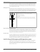
Tank flange Install the supplied gasket between the two flanges. Make sure that the mating
flange on the tank is level. Use gasket material between the flanges in order to make
minor adjustments.
Figure 4: Layout for a standard support plate with the vapor-proof option
4. Hand tighten the anchor bolts. Check the level and re-shim if necessary.
5. Tighten all anchor bolts in a star pattern in order to avoid distorting the support plate.
Piping checklists
General piping checklist
Precautions
CAUTION:
• Never draw piping into place by using force at the flanged connections of the pump. This can impose
dangerous strains on the unit and cause misalignment between the pump and driver. Pipe strain
adversely affects the operation of the pump, which results in physical injury and damage to the equipment.
• Vary the capacity with the regulating valve in the discharge line. Never throttle the flow from the
suction side. This action can result in decreased performance, unexpected heat generation, and
equipment damage.
Checklist
Check Explanation/comment Checked
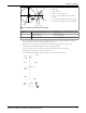
Check that all piping is supported
independently of, and lined up
naturally with, the pump flange.
This helps to prevent:
• Strain on the pump
• Misalignment between the pump and the drive unit
• Wear on the pump bearings and the coupling
• Wear on the pump bearings, seal, and shafting
Keep the piping as short as
possible.
This helps to minimize friction losses.
Check that only necessary fittings
are used.
This helps to minimize friction losses.
Do not connect the piping to the
pump until:
• The grout for the baseplate
or sub-base becomes hard.
• The hold-down bolts for the
pump and the driver are
tightened.
—
Make sure that all the piping
joints and fittings are airtight.
This prevents air from entering the piping system or
leaks that occur during operation.
Installation (Continued)
Model 3171 Installation, Operation, and Maintenance Manual 19