
User guide


1
2
3
4
5
6
7
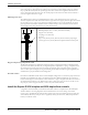
Figure 5: Location of the float, rod, and switch
1. Diameter of the coverplate (A)
2. Radius (B)
3. CL of the pump
4. Radius of 7.0 in. (178.0 mm)
5. 1.25 in. (31.8 mm) NPT float switch NTG
column
6. 0.38 in. (9.5 mm) NPT for the float rod guide
7. 8 in. (203.0 mm) diameter of float (standard)
Number Coverplate diameter (A) Radius (B)
1 22 in. (559 mm) 14.50 in. (368 mm)
2 26.50 in. (673 mm) 16.50 in. (419 mm)
3 31.00 in. (787 mm) 18.50 in. (470 mm)
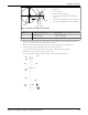
1. Before you install the pump in the sump, attach the lower guide arm (366) and the float rod guide
(336) to the correct suction cover bolt (based on the layout).
2. Thread the float switch support pipe (435) and the upper rod guide (337) into the pit cover.
3. Attach the float switch bracket (398) to the float switch support pipe.
You can rotate the float switch around the center line of the pump on the radius (B).
4. Install the float rod (334), float (342), and collars (335).
You must maintain the radius (4) between the float switch column and the float.
339
435
335
398
337
437
335
342
335
334
336
366
Installation (Continued)
Model 3171 Installation, Operation, and Maintenance Manual 27