
User guide


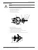


Assemble the rotating element
CAUTION:
Two people should handle any shaft over 9 feet long. Improper handling can bend the shaft.
136
382
112
370C
193B
134
369A
122
400
333
113
415
370D
361A
332A
M/MT/L
Only
1. For all groups except S/ST, install the retaining ring (369A) on the shaft (122).
2. Install the thrust bearing (112) on the shaft.
There are several methods that you can use in order to install bearings. The recommended method is
to use an induction heater that heats as well as demagnetizes the bearing.
CAUTION:
Wear insulated gloves when you use a bearing heater. Bearings get hot and can cause physical injury.
3. Install the lockwasher (382) on the shaft (122). Make sure that the tang of lockwasher is in the keyway
of the shaft.
4. Thread the locknut (136) onto the shaft and tighten the locknut until it is snug.
5. Bend any tang of the lockwasher into one of the slots on the locknut. Tighten the locknut if necessary
to align a lockwasher tab with a locknut slot.
6. Press the grease seal (333) into the bearing shell (134).
7. Slide the bearing shell onto the pump-end of the shaft and over the bearing.
8. Insert the retaining ring (361A) in the bearing shell groove. Make sure to keep the flat side against the
bearing.
9. Slide the labyrinth seal (332A) over the coupling-end of the shaft into the bearing shell until it is flush.
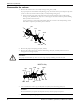
10. With the support plate in a vertical position, slide the shaft horizontally through the motor support.
Support the shaft and column with suitable stands.
11. Install the hold-down bolts (370C) and jacking bolts (370D) with jam nuts (415).
Assemble the column
If intermediate steady bearings are required, then you need additional column extensions (306) and steady
bearing housings (213).
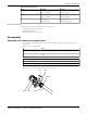
1. Prepare the steady bearing housing assemblies, if applicable.
You do not need to precisely center the steady bearing, and the holes in the bearing do not need to
line up with the holes in the housing. A recessed area inside the housing (213) allows lubricants to find
the opening in the bearing.
a) Remove the snap ring (369), if applicable.
b) Use a hydraulic press in order to press out the old steady bearing (197).
c) Press in the new steady bearing.
Maintenance (Continued)
46 Model 3171 Installation, Operation, and Maintenance Manual