
Manual


1
1. Sleeve puller.
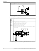
Remove the frame adapter from the frame (XL1, XL2-S, and XL2)
1. Thread a 20 mm eye bolt into the tapped hole provided at the top of the frame adapter (108) and sling
to a hoist.
2. Remove the eight hex head bolts (370B) from the frame adapter (108)
3. Gently tap the frame adapter from the frame (228) using a soft-blow hammer on the dry side of the
frame adapter.
228
370B
108
Disassemble the bearing frame
1. Secure the bearing-frame assembly firmly to a workbench.
2. Remove the coupling hub from the shaft by loosening the set screw (if provided) and using a puller.
3. Remove the coupling key (400).
4. Remove the coupling guard end plate by removing the bearing-housing adjuster screws (370C).
5. Remove the labyrinth shaft-seal assemblies (332A and 333A) from each end of the frame.
Maintenance
Models 3180, 3181, 3185, and 3186 Installation, Operation, and Maintenance Manual 81