Goulds Pumps Installation, Operation, and Maintenance Manual Model 3198 i-FRAME
Table of Contents Table of Contents Introduction and Safety...................................................................................................................................................4 Introduction.......................................................................................................................................................................4 Requesting other information..............................................................................................
Table of Contents Commissioning, Startup, Operation, and Shutdown............................................................................................39 Preparation for startup...................................................................................................................................................39 Remove the coupling guard...........................................................................................................................................
Table of Contents Bearing-frame inspection............................................................................................................................................76 C-face adapter inspection...........................................................................................................................................77 Seal chamber and stuffing box cover inspection.....................................................................................................
Introduction and Safety Introduction and Safety Introduction Purpose of this manual The purpose of this manual is to provide necessary information for: • Installation • Operation • Maintenance CAUTION: Read this manual carefully before installing and using the product. Improper use of the product can cause personal injury and damage to property, and may void the warranty. NOTICE: Save this manual for future reference, and keep it readily available at the location of the unit.
Introduction and Safety Safety terminology and symbols About safety messages It is extremely important that you read, understand, and follow the safety messages and regulations carefully before handling the product.
Introduction and Safety Environmental safety The work area Always keep the station clean to avoid and/or discover emissions. Waste and emissions regulations Observe these safety regulations regarding waste and emissions: • Appropriately dispose of all waste. • Handle and dispose of the processed liquid in compliance with applicable environmental regulations. • Clean up all spills in accordance with safety and environmental procedures. • Report all environmental emissions to the appropriate authorities.
Introduction and Safety • • • • • Use a lifting harness, a safety line, and a breathing device as required. Allow all system and pump components to cool before you handle them. Make sure that the product has been thoroughly cleaned. Disconnect and lock out power before you service the pump. Check the explosion risk before you weld or use electric hand tools. Precautions during work Observe these safety precautions when you work with the product or are in connection with the product: • Never work alone.
Introduction and Safety Product and product handling requirements These are the product and product handling requirements for Ex-approved products in potentially explosive atmospheres: • Only use the product in accordance with the approved motor data. • The Ex-approved product must never run dry during normal operation. Dry running during service and inspection is only permitted outside the classified area.
Introduction and Safety • Class III • Certified to Canadian and US requirements SERIAL NO.& YEAR OF MANUFACTURE HERE. Product warranty Coverage ITT undertakes to remedy faults in products from ITT under these conditions: • The faults are due to defects in design, materials, or workmanship. • The faults are reported to an ITT representative within the warranty period. • The product is used only under the conditions described in this manual.
Transportation and Storage Transportation and Storage Inspect the delivery Inspect the package 1. 2. 3. Inspect the package for damaged or missing items upon delivery. Note any damaged or missing items on the receipt and freight bill. File a claim with the shipping company if anything is out of order. If the product has been picked up at a distributor, make a claim directly to the distributor. Inspect the unit 1. 2. 3. 4. Remove packing materials from the product.
Transportation and Storage Pump type Lifting method Mounted on top of a Polyshield See separate information regarding the Polyshield ANSI Combo. ANSI Combo Examples Figure 1: Example of a proper lifting method NOTICE: Do not use this lifting method to lift a Polyshield ANSI Combo with the pump and motor mounted. Doing so may result in equipment damage. Figure 2: Example of a proper lifting method NOTICE: Do not use this lifting method to lift a Polyshield ANSI Combo with the pump and motor mounted.
Transportation and Storage NOTICE: When lifting a unit that does not have a way to secure the strap on the suction flange, you must secure the strap around the frame adapter. Failure to do so may result in equipment damage. Figure 4: Example of a proper lifting method with a strap secured around the frame adapter Storage guidelines Pump storage requirements Storage requirements depend on the amount of time that you store the unit. The normal packaging is designed only to protect the unit during shipping.
Product Description Product Description General description 3198 The 3198 is a horizontal overhung, open impeller, centrifugal pump. This pump is ANSI B73.1 compliant. It is made of a Teflon-lined ductile iron to handle severe corrosives. This model is based on 2 power ends and 4 hydraulic pump sizes. Figure 5: 3198 pump This table shows the number of hydraulic sizes available for each drive-unit size group.
Product Description Part description 3198 Casing Impeller Cover Power end 3196 3796 HT 3196 CV 3196 LF 3196 NM 3196 3198 Figure 6: 3198 part description This table describes the pump casing parts. Table 3: Casing Part Discharge Description Top-centerline Casing ventilation Self venting Gasket A teflon envelope with a compressible filler that provides a positive seal with a low bolt torque.
Product Description Cover Standard cover • The 318 is supplied with a PFA Teflon-lined cover to fit a clamped outside single seal Optional covers • a bolt-on metallic seal chamber for conventional back-to-back double seals • PFA Teflon-lined standard-bore stuffing-box cover is available for conventional single-clamped inside or outside seals. • For cartridge seals, an ETFE Tefzel-lined BigBore seal chamber is available. This table describes the main parts of the power end.
Product Description Temperature and vibration limits Variable Temperature Limit 195°F (91°C) Vibration 100% increase over the baseline level Battery life The i-ALERT Condition Monitor battery is not replaceable. You must replace the entire unit once the battery runs out of power. The battery life is not covered as part of the standard five-year pump warranty. This table shows the average condition monitor battery life under normal and alarm-mode operating conditions.
Product Description Nameplate on the pump casing using English units Table 5: Explanation of nameplate on the pump casing Nameplate field Explanation IMPLR. DIA. Impeller diameter, in inches MAX. DIA. Maximum impeller diameter, in inches GPM Rated pump flow, in gallons per minute FT HD Rated pump head, in feet RPM Rated pump speed, revolutions per minute MOD. Pump model SIZE Size of the pump STD. NO. ANSI standard designation MAT L. CONST. Material of which the pump is constructed SER. NO.
Product Description Nameplate field MAT L. CONST Explanation Material of which the pump is constructed SER. NO. Serial number of the pump MAX. DSGN KG/CM3 @ Kilograms per cubic centimeter at 20°C 20°C Nameplate on the bearing frame Table 7: Explanation of the nameplate on the bearing frame Nameplate field MOD. Explanation Pump model SIZE Size of the pump SER. NO.
Installation Installation Preinstallation Precautions WARNING: • When installing in a potentially explosive environment, make sure that the motor is properly certified. • You must earth (ground) all electrical equipment. This applies to the pump equipment, the driver, and any monitoring equipment. Test the earth (ground) lead to verify that it is connected correctly. NOTICE: Supervision by an authorized ITT representative is recommended to ensure proper installation.
Installation Foundation requirements Precautions CAUTION: If your pump is a Model NM3171, NM3196, 3198, 3298, V3298, SP3298, 4150, 4550, or 3107 there is a possible risk of static electric discharge from plastic parts that are not properly grounded. If the pumped fluid is non-conductive, drain and flush the pump with a conductive fluid under conditions that will not allow for a spark to be released to the atmosphere.
Installation Baseplate-mounting procedures Prepare the baseplate for mounting 1. 2. 3. 4. 5. Remove all the attached equipment from the baseplate. Clean the underside of the baseplate completely. If applicable, coat the underside of the baseplate with an epoxy primer. Use an epoxy primer only if you used an epoxy-based grout. Remove the rust-proofing coat from the machined mounting pads using an appropriate solvent. Remove water and debris from the foundation-bolt holes.
Installation 6. These are the leveling tolerances: • A maximum difference of 0.125 in. (3.2 mm) lengthwise • A maximum difference of 0.059 in. (1.5 mm) across You can use the baseplate-leveling worksheet when you take the readings. Hand-tighten the nuts for the foundation.
Installation 1 3 4 1. 2. 3. 4. 5. 6. 4. 5. 2 6 5 Machinist's levels Driver's mounting pads Foundation bolts Jackscrews Grout hole Pump's mounting pads Turn the center jackscrews down so that they rest on their plates on the foundation surface. Level the pump mounting pads: NOTICE: Remove all dirt from the mounting pads in order to make sure that you achieve the correct leveling. Failure to do so can result in equipment damage or decreased performance.
Installation 2. 3. 4. 5. 6. 7. 8. Install the lower part of the spring assembly: a) Screw the lower jam nut onto the spring stud. b) Screw the lower adjusting nut onto the spring-stud, on top of the jam nut. c) Set the lower adjusting nut to the correct height. The correct height depends on the required distance between the foundation/floor and the baseplate. d) Put a washer, a follower, a spring, and one more follower onto the lower adjusting nut.
Installation 2. Install the lower part of the stilt assembly: a) Screw the lower jam nut and adjusting nut onto the stilt. b) Set the lower adjusting nut to the correct height. The correct height depends on the required distance between the foundation/floor and the baseplate. c) Put a washer onto the lower adjusting- nut. Install the stilt assembly on the baseplate: a) Insert the stilt assembly into the baseplate's anchorage hole from below. b) Put a washer onto the stilt.
Installation Baseplate-leveling worksheet Level measurements 1)____________________ 2)____________________ 3 5 3)____________________ 7 8 4)____________________ 9 2 4 5)____________________ 6)____________________ 6 7)____________________ 1 8)____________________ 9)____________________ 10)___________________ 11)___________________ 14 10 17 15 16 11 12 13 18 12)___________________ 13)___________________ 14)___________________ 15)___________________ 16)___________________ 17)_____________
Installation Install the pump, driver, and coupling 1. 2. 3. Mount and fasten the pump on the baseplate. Use applicable bolts. Mount the driver on the baseplate. Use applicable bolts and hand tighten. Install the coupling. See the installation instructions from the coupling manufacturer. Pump-to-driver alignment Precautions WARNING: • Follow shaft alignment procedures in order to prevent catastrophic failure of drive components or unintended contact of rotating parts.
Installation Final alignment (hot alignment) checks When Why After the first run This ensures correct alignment when both the pump and the driver are at operating temperature. Periodically This follows the plant operating procedures. Permitted indicator values for alignment checks NOTICE: The specified permitted reading values are valid only at operating temperature. For cold settings, other values are permitted. You must use the correct tolerances.
Installation Guideline Explanation Make sure that the hold-down bolts for the driver feet are loose before you make alignment corrections. This makes it possible to move the driver when you make alignment corrections. Check the alignment again after any mechanical adjustments. This corrects any misalignments that an adjustment may have caused. Attach the dial indicators for alignment You must have two dial indicators in order to complete this procedure. 1.
Installation X Y Shims Figure 11: Side view of an incorrect vertical alignment 4. Repeat the previous steps until the permitted reading value is achieved. Perform angular alignment for a horizontal correction 1. 2. 3. Set the angular alignment indicator (A) to zero on left side of the driver coupling half (Y), 90° from the top-center position (9 o’clock). Rotate the indicator through the top-center position to the right side, 180° from the start position (3 o’clock). Record the indicator reading.
Installation When the reading Then... value is... Negative The pump coupling half (X) is lower than the driver coupling half (Y). Remove shims of a thickness equal to half of the indicator reading value under each driver foot. Positive The pump coupling half (X) is higher than the driver coupling half (Y). Add shims of a thickness equal to half of the indicator reading value to each driver foot. NOTICE: You must use an equal amount of shims with each driver foot to prevent misalignment.
Installation Perform complete alignment for a vertical correction A unit is in complete alignment when both the angular indicator (A) and the parallel indicator (P) do not vary by more than 0.002 in. (0.05 mm) as measured at four points 90° apart. 1. Set the angular and parallel dial indicators to zero at the top-center position (12 o’clock) of the driver coupling half (Y). 2. Rotate the indicators to the bottom-center position (6 o’clock). 3. Record the indicator readings. 4.
Installation Specified limits A C-face adapter can attain a nominal alignment of 0.007 in. Total Indicated Runout (T.I.R.). However, because of the stack-up of the machining tolerances of the various parts, the alignment can be as high as 0.015 inches TIR. If high reliability (with shaft alignments of less than 0.002 in. (0.05mm)) is required for the pump, use a foot-mounted drive unit on a precision-machined baseplate and perform a conventional alignment.
Installation Piping checklists General piping checklist Precautions CAUTION: • Never draw piping into place by using force at the flanged connections of the pump. This can impose dangerous strains on the unit and cause misalignment between the pump and driver. Pipe strain adversely affects the operation of the pump, which results in physical injury and damage to the equipment. • Vary the capacity with the regulating valve in the discharge line. Never throttle the flow from the suction side.
Installation Example: Installation for expansion Correct Incorrect 1 1. Expansion loop/joint Fastening WARNING: • Only use fasteners of the proper size and material. • Replace all corroded fasteners. • Make sure that all fasteners are properly tightened and that there are no missing fasteners. Suction-piping checklist Performance curve reference Net positive suction head available (NPSHA) must always exceed NPSH required (NPSHR) as shown on the published performance curve of the pump.
Installation Check Explanation/comment Check that the eccentric reducer at the suction flange of the pump has the following properties: • Sloping side down • Horizontal side at the top See the example illustrations. If suction strainers or suction bells are used, check that they are at least three times the area of the suction piping. Suction strainers help to prevent clogging. Mesh holes with a minimum diameter of 1/16 in. (1.6 mm) are recommended.
Installation Example: Elbow close to the pump suction inlet Correct Incorrect The correct distance between the inlet flange of the pump and the closest elbow must be at least five pipe diameters. 1 2 1. 2. Enough distance to prevent cavitation Eccentric reducer with a level top Example: Suction piping equipment Correct Incorrect 1 1 2 5 4 3 1. 2. 3. 4. 5. Suction pipe sloping upwards from liquid source Long-radius elbow Strainer Foot valve Eccentric reducer with a level top 1.
Installation Check Explanation/comment Check that a check valve is installed in the discharge line, between the isolation valve and the pump discharge outlet. The location between the isolation valve and the pump allows inspection of the check valve. The check valve prevents damage to the pump and seal due to the back flow through the pump, when the drive unit is shut off. It is also used to restrain the liquid flow. See Example: Discharge piping equipment for illustrations.
Commissioning, Startup, Operation, and Shutdown Commissioning, Startup, Operation, and Shutdown Preparation for startup WARNING: • Failure to follow these precautions before you start the unit will lead to serious personal injury and equipment failure. • Do not operate the pump below the minimum rated flows or with the suction or discharge valves closed. These conditions can create an explosive hazard due to vaporization of pumped fluid and can quickly lead to pump failure and physical injury.
Commissioning, Startup, Operation, and Shutdown Driver 3. 4. Remove the nut, bolt, and washers from the driver half of the coupling guard. Remove the driver-side end plate. Driver 5. 40 Driver-side end plate Remove the driver half of the coupling guard: a) Slightly spread the bottom apart. b) Lift upwards.
Commissioning, Startup, Operation, and Shutdown Driver-side coupling guard Annular groove Driver 6. 7. Remove the remaining nut, bolt, and washers from the pump half of the coupling guard. It is not necessary to remove the end plate from the pump side of the bearing housing. You can access the bearing-housing tap bolts without removing this end plate if maintenance of internal pump parts is necessary. Remove the pump half of the coupling guard: a) Slightly spread the bottom apart. b) Lift upwards.
Commissioning, Startup, Operation, and Shutdown Check the rotation WARNING: • Operating the pump in reverse rotation can result in the contact of metal parts, heat generation, and breach of containment. • Always disconnect and lock out power to the driver before you perform any installation or maintenance tasks. Failure to disconnect and lock out driver power will result in serious physical injury. 1. 2. 3. 4. 5. 6. Lock out power to the driver.
Commissioning, Startup, Operation, and Shutdown Impeller-clearance setting Importance of a proper impeller clearance A proper impeller clearance ensures that the pump runs at high performance. WARNING: • The impeller clearance setting procedure must be followed. Improperly setting the clearance or not following any of the proper procedures can result in sparks, unexpected heat generation, and equipment damage.
Commissioning, Startup, Operation, and Shutdown Refer to the impeller clearance table to determine the correct clearance. Tighten the bolts evenly in this order: a) Tighten the locking bolts (370C). b) Tighten the jack bolts (370D). Make sure to keep the indicator reading at the proper setting. 10. Make sure the shaft turns freely. 9.
Commissioning, Startup, Operation, and Shutdown Couplings must have proper certification to be used in an ATEX classified environment. Use the instructions from the coupling manufacturer in order to lubricate and install the coupling. Install the coupling guard WARNING: • Never operate a pump without a properly installed coupling guard. Personal injury will occur if you run the pump without a coupling guard.
Commissioning, Startup, Operation, and Shutdown 2 1 3 4 1. 2. 3. 4. 3. 46 Driver Pump end plate Bearing housing Jam nut Put the pump-half of the coupling guard in place: a) Slightly spread the bottom apart. b) Place the coupling guard half over the pump-side end plate.
Commissioning, Startup, Operation, and Shutdown 4 1 3 2 1. 2. 3. 4. Annular groove Pump-side end plate Driver Pump half of the coupling guard The annular groove in the coupling guard half must fit around the end plate. 1 2 3 1. 2. 3. 4. Annular groove End plate (pump end) Guard half Use a bolt, a nut, and two washers to secure the coupling guard half to the end plate. Tighten securely. 1 1. 2. 3. 5.
Commissioning, Startup, Operation, and Shutdown b) Place the driver half of the coupling guard over the pump half of the coupling guard. The annular groove in the coupling guard half must face the motor. Annular groove Guard half Driver 6. Place the driver-side end plate over the motor shaft. Driver 7. 8. 9. 48 End plate Place the driver-side end plate in the annular groove of the driver-half of the coupling guard.
Commissioning, Startup, Operation, and Shutdown Driver Slide to fit 10. Use a nut, a bolt, and two washers to secure the coupling guard halves together. 11. Tighten all nuts on the guard assembly. WARNING: Never operate the pump without the coupling guard correctly installed. Bearing lubrication WARNING: Make sure to properly lubricate the bearings. Failure to do so can result in excess heat generation, sparks, and premature failure.
Commissioning, Startup, Operation, and Shutdown Temperature Bearing temperatures exceed 180°F (82°C) Oil requirement Use ISO viscosity grade 100 with bearing-frame cooling or finned-tube oil cooler. The finned-tube oil cooler is standard with the HT 3196 model and optional for all other models. Pumped-fluid temperatures exceed 350°F (177°C) Use synthetic lubrication.
Commissioning, Startup, Operation, and Shutdown 3. Replace the fill plug. Lubricate the bearings with pure oil mist Oil mist is an optional feature for this pump. • To lubricate bearings with pure oil mist, follow the instructions provided by the manufacturer of the oil-mist generator. The inlet connections are on the top of the bearing frame. Greased-for-life bearing lubrication The bearing manufacturer fills greased-for-life bearings with grease and seals them at the factory.
Commissioning, Startup, Operation, and Shutdown Packed stuffing box option WARNING: Packed stuffing boxes are not allowed in an ATEX-classified environment. The factory does not install the packing, lantern ring, or split gland. These parts are included with the pump in the box of fittings. Before you start the pump, you must install the packing, lantern ring, and split gland according to the Packed stuffing box maintenance section in the Maintenance chapter.
Commissioning, Startup, Operation, and Shutdown This illustration is an example of priming the pump with a foot valve and an outside supply: 1 2 3 5 4 1. 2. 3. 4. 5. Discharge isolation valve Shutoff valve From outside supply Foot valve Check valve This illustration is an example of priming the pump with a foot valve using a bypass around the check valve: 1 5 2 4 3 1. 2. 3. 4. 5.
Commissioning, Startup, Operation, and Shutdown Other methods of priming the pump You can also use these methods in order to prime the pump: • Prime by ejector • Prime by automatic priming pump Start the pump CAUTION: • Immediately observe the pressure gauges. If discharge pressure is not quickly attained, stop the driver, reprime, and attempt to restart the pump. • Observe the pump for vibration levels, bearing temperature, and excessive noise.
Commissioning, Startup, Operation, and Shutdown Place a small magnet on the condition monitor over the ITT logo and then remove it, as this example shows. Magnet 761B When the condition monitor is activated it: 1. Displays a series of red LEDs followed by a solid green LED. 2. Collects eight samples that are spaced one second apart. 3. Averages these readings to establish the baseline vibration level. 4. Flashes a green LED after approximately twelve seconds.
Commissioning, Startup, Operation, and Shutdown Pump operation precautions General considerations CAUTION: • Vary the capacity with the regulating valve in the discharge line. Never throttle the flow from the suction side since this can result in decreased performance, unexpected heat generation, and equipment damage. • Do not overload the driver. Driver overload can result in unexpected heat generation and equipment damage.
Commissioning, Startup, Operation, and Shutdown Deactivate the i-ALERT™ Condition Monitor NOTICE: Always deactivate the condition monitor when the pump is going to be shut down for an extended period of time. Failure to do so will result in reduced battery life. 1. 2. Touch and hold a small magnet to the condition monitor over the ITT logo until the red LEDs blink three times.
Maintenance Maintenance Maintenance schedule Maintenance inspections A maintenance schedule includes these types of inspections: • Routine maintenance • Routine inspections • Three-month inspections • Annual inspections Shorten the inspection intervals appropriately if the pumped fluid is abrasive or corrosive or if the environment is classified as potentially explosive. Routine maintenance Perform these tasks whenever you perform routine maintenance: • Lubricate the bearings. • Inspect the seal.
Maintenance Bearing maintenance These bearing lubrication sections list different temperatures of the pumped fluid. If the pump is ATEXcertified and the temperature of the pumped fluid exceeds the permitted temperature values, then consult your ITT representative. Bearing lubrication schedule Type of bearing Oil-lubricated bearings Grease-lubricated bearings First lubrication Add oil before you install and start the pump. Change the oil after 200 hours for new bearings.
Maintenance Exxon Teresstic 220 Mobil DTE Oil BB Mobil Gear 630 Shell Marlina 220 Tellus 220 Sunoco Sunvis 9220 Texaco Regal R&O 220 Rando HD 220 Royal Purple Synfilm GT 220 Synergy 220 Regrease the grease-lubricated bearings NOTICE: Make sure that the grease container, the greasing device, and the fittings are clean. Failure to do this can result in impurities entering the bearing housing when you regrease the bearings. 193 113 1. 2. 3. 4. 5. 6. 7. Wipe dirt from the grease fittings.
Maintenance Lubricating-grease requirements Precautions NOTICE: • Never mix greases of different consistencies (NLGI 1 or 3 with NLGI 2) or with different thickeners. For example, never mix a lithium-based grease with a polyurea-based grease. Doing so may result in decreased performance. • Remove the bearings and old grease if you need to change the grease type or consistency. Failure to do so may result in equipment damage or decreased performance.
Maintenance Reference drawing The manufacturer supplies a reference drawing with the data package. Keep this drawing for future use when you perform maintenance and seal adjustments. The seal drawing specifies the required flush fluid and attachment points. Before you start the pump Check the seal and all flush piping. Mechanical seal life The life of a mechanical seal depends on the cleanliness of the pumped fluid.
Maintenance • Torque wrench with sockets • Wrenches Drain the pump CAUTION: • Allow all system and pump components to cool before you handle them to prevent physical injury. • If your pump is a Model NM3171, NM3196, 3198, 3298, V3298, SP3298, 4150, 4550, or 3107 there is a possible risk of static electric discharge from plastic parts that are not properly grounded.
Maintenance 1. Is your bearing frame oil lubricated? • If No: Proceed to step 2. • If Yes: 1. Remove the bearing-frame drain plug (408A) in order to drain oil from the bearing frame. 2. Replace the plug after the oil is drained. 3. Remove the oil reservoir, if equipped. 408A NOTICE: Oil analysis should be part of a preventive maintenance program that determines the cause of a failure. Save the oil in a clean container for inspection.
Maintenance 2. Does your pump use a C-face adapter? • If Yes: Place one sling from the hoist through the frame adapter (108) or frame (228A) for the STi and a second sling from the hoist through the C-face adapter. • If No: Place a sling from the hoist through the frame adapter (108) or the frame (228A) for the STi. 370 108 370F 100 340 351 418 3. 4. Remove the hold-down bolts of the bearing frame foot. Remove the casing bolts.
Maintenance Clean surfaces prevent the casing gasket from partially adhering to the casing due to binders and adhesives in the gasket material. Remove the coupling hub 1. 2. Clamp the frame adapter securely to the workbench. Remove the coupling hub. Mark the shaft for relocation of the coupling hub during reassembly. Impeller removal Remove the impeller ( STi , MTi , and ) WARNING: Never apply heat to remove an impeller.
Maintenance Shaft Wrench 101 4. 5. Repeat step 3 until the impeller becomes loose. Remove and discard the impeller O-ring (412A). You will insert a new O-ring during reassembly. 412A Figure 16: O-ring for models 3196, HT 3196, NM 3196, 3198, and 3796 If the impeller cannot be removed by the previous methods, cut the shaft between the gland and the frame, remove the impeller, stuffing-box cover, gland, sleeve, and shaft end as a unit. Do not apply heat.
Maintenance 250 184 355 370H 4. Remove the shaft sleeve (126). The mechanical seal is attached to the sleeve. 5. 6. Loosen the set screws and slide the rotary portion off the sleeve. On the 3198, remove the Teflon sleeve: a) Remove the mechanical seal from the sleeve. b) Slice the sleeve lengthwise with a sharp knife. Remove the stationary seat and the gland or the seal chamber with the gland gaskets. 7.
Maintenance Remove the inboard labyrinth oil seal Labyrinth oil-seal O-rings are part of the 3196 maintenance kits, and they are sold separately. 1. Determine the fit of your labyrinth oil seal. Table 10: Labyrinth oil-seal fit Model STi Type of fit O-ring fit into the bearing-frame adapter (228A) MTi O-ring fit into the frame adapter 2. Remove the O-rings (497H and 497J) and the seal (333A). 497H 497J 108 333A Power-end disassembly Disassemble the power end ( STi , MTi ) 1. 2. 3.
Maintenance 370D 423 134 361A 168A 496 7. Remove the bearing housing (134) and bearings (112A and 168A) from the shaft (122). 134 112 361A 168A 122 8. Remove the bearing locknut (136) and bearing lock washer (382). 9. Remove the inboard bearing (168A). 10. Remove the outboard bearing (112A). NOTICE: Use force only on the inner race when you press bearings off the shaft. Do not use force in situations in which you might break a part. Doing so may result in equipment damage.
Maintenance 423 134 228A 370D 370C 4. Remove the jack screws (370D) with the nuts (423). 236A 134 370D 496 253B 423 5. 6. 7. Remove the bearing housing O-ring (496). Remove the clamp ring screws (236A) and separate the clamp ring (253B) from the bearing housing (134). You must remove the bearings before you can remove the clamp ring from the shaft. Remove the bearing housing (134) and the bearings (112A and 168A) from the shaft (122). 250 184 355 370H 8. Remove the inboard bearing (168A).
Maintenance 122 168A 382 136 253B 112A 9. Remove the bearing locknut (136) and bearing lockwasher (382). 10. Remove the outboard bearings (112A). NOTICE: Use force only on the inner race when you press bearings off the shaft. Do not use force in situations in which you might break a part. Doing so may result in equipment damage. NOTICE: Save the bearings for inspection. Do not reuse the bearings. Doing so may result in decreased performance. 11.
Maintenance 372T 113A 408W 408W 761B 408N 319 408M 408N 408A 241 370F Guidelines for i-ALERT™ Condition Monitor disposal Precautions WARNING: • Never heat the condition monitor to temperatures in excess of 300°F (149°C). Heating to these temperatures could result in death or serious injury. • Never dispose of the condition monitor in a fire. This could result in death or serious injury.
Maintenance Pre-assembly inspections Guidelines Before you assemble the pump parts, make sure you follow these guidelines: • Inspect the pump parts according to the information in these pre-assembly topics before you reassemble your pump. Replace any part that does not meet the required criteria. • Make sure that the parts are clean. Clean the pump parts in solvent in order to remove oil, grease, and dirt. NOTICE: Protect machined surfaces while you clean the parts.
Maintenance Impeller parts Vane edges When to replace When you see cracks, pitting, or corrosion damage Impeller areas to inspect c a b c 101 Figure 20: Areas to inspect for wear on the 3196 impeller. Frame adapter check and replacement • Replace the frame adapter if it has cracks or excessive corrosion damage. • Make sure the gasket surface is clean. The 3198 frame adapter is not interchangeable with the adapter from any other model.
Maintenance Sleeve fit in inches (millimeters) 0.002 (0.051) Without sleeve Coupling fit in inches (millimeters) 0.001 (0.025) Shaft and sleeve check 126 • Check the shaft and sleeve (126) surface for grooves and pitting. • Replace the shaft and sleeve if any grooves or pits are found. Bearing-frame inspection Checklist Check the bearing frame for these conditions: • Visually inspect the bearing frame and frame foot for cracks. • Check the inside surfaces of the frame for rust, scale, or debris.
Maintenance 241 Figure 22: Inside surface inspection locations C-face adapter inspection Checklist • Visually inspect the C-face adapter (340) for cracks. • Check all surfaces for rust, scale, or debris and remove all loose and foreign material. • Check for corrosion or pitting. This figure shows the areas to inspect for cracks on the C-face adapter.
Maintenance These images point to the areas to inspect: 184 Figure 24: BigBoreTM chamber 184 Figure 25: Stuffing box cover 444 Figure 26: Dynamic-seal backplate 78 Model 3198 i-FRAME Installation, Operation, and Maintenance Manual
Maintenance 184 Figure 27: TaperBoreTM Plus 444 Figure 28: 3198 backplate 159 Figure 29: 3198 seal chamber Model 3198 i-FRAME Installation, Operation, and Maintenance Manual 79
Maintenance 184 ™ Figure 30: 3198 BigBoreTM Bearings inspection Condition of bearings Do not reuse bearings. The condition of the bearings provides useful information on operating conditions in the bearing frame. Checklist Perform these checks when you inspect the bearings: • Inspect the bearings for contamination and damage. • Note any lubricant condition and residue. • Inspect the ball bearings to see if they are loose, rough, or noisy when you rotate them.
Maintenance 134 Figure 31: STi and MTi bearing housing Bearing fits and tolerances This table references the bearing fits and tolerances according to the ABEC I standard. Table 13: Bearing fits and tolerances table STi inches (millimeters) MTi inches (millimeters) LTi inches (millimeters) XLT-i, i-17 inches (millimeters) Shaft OD Inboard 1.3785 (35.014) 1.3781 (35.004) 1.7722 (45.014) 1.7718 (45.004) 2.1660 (55.016) 2.1655 (55.004) 2.5597 (65.016) 2.5592 (65.004) Clearance 0.0010 (0.
Maintenance Reassembly Assemble the rotating element and the bearing frame ( STi and MTi ) CAUTION: Wear insulated gloves when you use a bearing heater. Bearings get hot and can cause physical injury. NOTICE: Make sure that the pipe threads are clean, and that you apply thread sealant to the plugs and fittings. Failure to do so may result in equipment damage or decreased performance. NOTICE: Use an induction heater that heats as well as demagnetizes the bearings when you install bearings.
Maintenance 3. 4. 5. 6. 7. 8. f) Position the bearing (112) on the shaft (122) against the shoulder and snug the locknut (136) against the bearing until it is cool. The locknut prevents the bearing from moving away from the shaft shoulder as it cools. g) Remove the bearing locknut (136) after the bearing (112) cools. Put the lockwasher (382) onto the shaft (122). Thread the locknut (136) onto the shaft (122) and tighten it until it is snug. Bend the tangs of the lockwasher into the slots of the locknut.
Maintenance a) Coat the outside of the bearing housing (134) with oil. b) Coat all the internal surfaces of the bearing frame (228) with oil. c) Install the shaft assembly into the bearing frame (228). Make sure that the shaft rotates freely. d) Install the clamp bolts (370C) in the bearing housing (134) and tighten by hand. e) Install the jack bolts (370D) with the locknuts (423) in the bearing housing (134) and tighten by hand.
Maintenance 372T 113A 408W 408W 761B 408N 319 408M 408N 408A 241 370F 2. Install the outboard bearings (112A) on the shaft (122). The regreasable bearing has a single shield. Make sure that the bearing is installed with the shield away from the impeller. The duplex bearings are mounted back-to-back. Make sure that the orientation of the bearings are correct. a) Inspect the shaft (122) to ensure that it is clean, dimensionally correct, and is free of nicks and burrs. 122 112 136 b) c) d) e) 3.
Maintenance 122 168A 382 136 253B 112A 9. Install the bearing housing as follows (see the illustration): a) Coat the outside of the outboard bearing (112A) with oil. b) Coat the bore of the bearing housing (134) with oil. c) Put the bearing housing (134) onto the shaft. Do not use force. 122 253B 134 168A 112A 10. Prepare the shaft for assembly as follows (see the illustration): a) Place the bearing-clamp ring (253B) onto the shaft (122). b) Fasten the clamp-ring bolts (236A) crosswise.
Maintenance a) Coat the outside of the bearing housing (134) with oil. b) Coat all the internal surfaces of the bearing frame (228) with oil. c) Install the shaft assembly into the bearing frame (228). Make sure that the shaft rotates freely. d) Install the clamp bolts (370C) in the bearing housing (134) and tighten by hand. e) Install the jack bolts (370D) with the locknuts (423) in the bearing housing (134) and tighten by hand. Assemble the frame 1. 2.
Maintenance 4. Check the frame-face runout by rotating the shaft so that the indicator measures the fit for 360º. If the total indicator reading is greater than 0.001 in. (0.025 mm), then disassemble and determine the cause. 5. Place the manila gasket (360D) on the frame (228), and hold the gasket in place by inserting the dowel pins (469B) in their holes. The gasket is designed to fit only one way. Install the frame adapter. a) Place the frame adapter (108) onto the frame assembly.
Maintenance 360D 108 496B 370B c) Install the dowel pins (469B) and bolts (370B). Tighten the bolts in a criss-cross pattern according to the specifications in the bolt torque values table. d) Rotate the shaft 360º to check the adapter fit. If the total indicator reading is greater than 0.005 in. (0.13 mm), then determine the cause and correct it before you proceed. 7. 8. Install the labyrinth oil-seal (333A) into the adapter (108) and the bearing frame (228). The labyrinth oil seal is an O-ring fit.
Maintenance 333A INPRO labyrinth oil seal description Description The INPRO VBXX-D Labyrinth Oil Seal consists of the rotor (1), the stator (2), and the VBX Ring (3). The rotor (1) fits over the shaft and is held in place by an elastomeric drive ring (4). The drive ring causes the rotor to turn with the shaft and provides a positive, static seal against the shaft. Since there is no metalto-metal contact, there are no friction or wear concerns. NOTICE: The INPRO VBX is a one-piece design.
Maintenance NOTICE: The edges of the keyway can be sharp. Make sure to cover the keyway with tape. Failure to do so may result in cutting the O-ring and damaging the seal. 2. 3. 4. 5. Lightly lube the shaft and the drive ring (4) with lubricant. Lubricant helps in the installation process. Be sure that the lubricant is compatible with the O-ring material and the pump-system standards.
Maintenance Seal the shaft with a cartridge mechanical seal WARNING: The mechanical seal used in an Ex-classified environment must be properly certified. Prior to startup, make sure that all areas that could leak pumped fluid to the work environment are closed. NOTICE: The mechanical seal must have an appropriate seal-flush system. Otherwise, excess heat generation and seal failure can occur. 1. 2. 3. 4. 5. 6. 7.
Maintenance Rotate the indicator through 360º. If the total indicator reading is greater than 0.005 inches (0.13 mm), determine the cause and correct the issue before you proceed. c) Install the shaft sleeve (126). 126 412A 101 2. 3. 4. Mark the shaft and sleeve at the face of the seal chamber. Continue the complete reassembly of the pump, except for the mechanical seal. Set the impeller clearance. Refer to the Impeller Clearance Setting section for more information. 5.
Maintenance Seal the shaft with a conventional outside-component mechanical seal WARNING: The mechanical seal used in an Ex-classified environment must be properly certified. Prior to startup, make sure that all areas that could leak pumped fluid to the work environment are closed. NOTICE: The mechanical seal must have an appropriate seal-flush system. Otherwise, excess heat generation and seal failure can occur. 1. Assemble the seal chamber.
Maintenance 126 412A 101 2. 3. 4. Mark the shaft and sleeve at the face of the seal chamber. Continue the complete reassembly of the pump, except for the mechanical seal. Set the impeller clearance. Refer to the Impeller clearance setting section for more information. 5. Scribe a line on the marked shaft and sleeve at the face of the seal chamber. 6. Remove the casing, the impeller, and the seal chamber. 7. Install the mechanical-seal rotary unit per the manufacturer's instructions.
Maintenance 101 3. 4. Loosen the clamp bolts (370C) and the jack bolts (370D). Measure the gap between the impeller (101) and the seal chamber and stuffing-box cover (184) with a feeler gauge. 423 370C 370D 5. 6. 96 When you reach a 0.030 in. (0.76 mm) clearance, tighten the clamp bolts (370C), jack bolts (370D), and lock nuts (423). This approximates the impeller position when it is set to 0.015 in. (0.38 mm) from the casing.
Maintenance .030 101 For more information on how to set the impeller clearances, refer to the Impeller-clearance checks and Impeller-clearance setting sections in Commissioning, Startup, Operation, and Shutdown. Attach the i-ALERT™ Condition Monitor to the pump CAUTION: Always wear protective gloves. The pump and condition monitor can be hot. Tools required: • 5/32 inch hex wrench 1. Attach the condition monitor (761B) to the bearing frame (228A) using the hex-head screw (372T) provided.
Maintenance Post-assembly checks Perform these checks after you assemble the pump, then continue with pump startup: • Rotate the shaft by hand in order to make sure that it rotates easily and smoothly and that there is no rubbing. • Open the isolation valves and check the pump for leaks. Install the back pull-out assembly (except HT 3196) CAUTION: Never remove the back pull-out assembly without assistance. 1. 2.
Maintenance 100 351 418 100 340 351 418 4. 5. Install and then hand-tighten the casing bolts (370). Refer to the bolt torque values for information on how to tighten the casing bolts. Install and tighten the casing jackscrews (418). NOTICE: Do not overtighten the casing jackscrews. Doing so may result in equipment damage.
Maintenance 370 108 370F 6. Reinstall the shims under the frame foot and tighten the frame foot to the baseplate. Make sure that you use the proper shim. Mount a dial indicator in order to measure the distance between the top of the frame and the baseplate. Make sure that the distance does not change as you tighten the frame-foot bolts. 7. Check the total clearance of the impeller in the casing. With new parts, an acceptable range is 0.030 in. (0.76 mm) to 0.065 in. (1.65 mm).
Maintenance Location Frame 3196, CV 3196, LF 3196, 3796 Lube Dry NM 3196 3198 Lube Dry Lube Dry Bearing end cover bolts XLT-i, i17 9 (12) (371C) 12 (16) N/A N/A N/A N/A STi, MTi, 55* (6.2) Dynamic seal capscrews LTi (265) XLT-i, i17 9 (12) 83* (9.4) N/A N/A N/A N/A 12 (16) N/A N/A N/A N/A * Values are in lb-in. (Nm) This table provides the maximum torque values for casing bolts.
Maintenance • • • • • • • • • • • • • • • • • • Shaft sleeve (126) Outboard bearing (112A) Inboard bearing (168A) Casing gasket (351) Frame-to-adapter gasket (360D) Bearing-housing retaining ring (361A) Bearing lockwasher (382) Bearing locknut (136) Impeller O-ring (412A) Bearing-housing O-ring (496) Outboard labyrinth-seal rotary O-ring (497F) Outboard labyrinth-seal stationary O-ring (497G) Inboard labyrinth-seal rotary O-ring (497H) Inboard labyrinth-seal stationary O-ring (497J) Lantern ring half (105
Maintenance This table shows which brand of grease to use when lubricating the pump. Table 22: Lubricating-grease requirements NGLI consistency Pumpage temperature less than Pumpage temperature greater 350°F (177°C) than 350°F (177°C) 2 3 Mobil Mobilux EP2 SCH32 Exxon Unirex N2 Unirex N3 Sunoco Mutipurpose 2EP N/A SKF LGMT 2 LGMT 3 Convert from greased-for-life or regreaseable to oil-lubricated bearings 1.
Maintenance Item Number Size Description Quantity 193 1/4"-18 NPT Grease fitting 2 228 ---- Bearing frame 1 241 ---- Frame foot 1 370F 1/2" Hex cap screw 2 408A 3/8"-18 NPT External square head pipe 1 plug (magnetic) 408J 1/4"-18 NPT External hex/square head 1 pipe plug 408L 1/2"-14 NPT Square countersunk headless pipe plug 1 408M 1" 11-1/2" NPT Square countersunk headless pipe plug 1 529 1/2" Light helical spring lock washer 2 Conversion from flood-oil to pure-oil mis
Maintenance CAUTION: The oven and sleeve are hot. Failure to use insulated gloves could result in burns and other physical injuries. 4. 5. Remove the sleeve from the oven. Slide the sleeve onto the shaft immediately after you remove it from the oven. Push the sleeve onto the shaft until the sleeve bottoms out on the shoulder of the shaft. The hook end of the sleeve extends beyond the knurled portion of the shaft. 6. The length of the sleeve shrinks as it cools.
Troubleshooting Troubleshooting Operation troubleshooting Symptom Cause The pump is not delivering The pump is not primed. liquid. Remedy Re-prime the pump and check that the pump and suction line are full of liquid. The suction line is clogged. Remove the obstructions. The impeller is clogged. Back-flush the pump in order to clean the impeller. The shaft is rotating in the wrong direction. Change the rotation. The rotation must match the arrow on the bearing housing or pump casing.
Troubleshooting Symptom The stuffing box is leaking excessively. The motor requires excessive power. Cause The packing gland is not adjusted properly. Remedy Tighten the gland nuts. The stuffing box is not packed properly. Check the packing and repack the box. The mechanical seal parts are worn. Replace the worn parts. The mechanical seal is overheating. Check the lubrication and cooling lines. The shaft sleeve is scored. Machine or replace the shaft sleeve as necessary.
Troubleshooting i-ALERT™ Condition Monitor troubleshooting Symptom Cause Remedy There are no green or red flashing LEDs. The battery is dead. Replace the condition monitor. The unit is deactivated. Activate the condition monitor. The unit is malfunctioning. Consult your ITT representative for a warranty replacement. The baseline is bad. Check the temperature and vibration levels and reset the condition monitor. The unit is malfunctioning.
Parts Listings and Cross-Sectional Drawings Parts Listings and Cross-Sectional Drawings Parts list Table 24: Construction material and quantity (continued) Item Quantity Part name 100 1 Casing Pump Material (3196, HT 3196, CV 3196, 3796) All Titanium 1220 101 1 Impeller 1220 6929 6944 105 1 Lantern Ring Teflon – – 106 1 set Stuffing Box Packing Non-asbestos braid – – 107 1 Gland—Packed Box 1220 – – 108 1 Frame Adapter 1013 109C 1*** Outboard Bearing End Cover 1001 112A
Parts Listings and Cross-Sectional Drawings Item Quantity Part name 360C 1 *** Gasket—Thrust End Cover Pump Material (3196, Pump Material (NM Pump Material HT 3196, CV 3196, 3196) (3198) 3796) All Titanium Vinylester D.I.
Parts Listings and Cross-Sectional Drawings Item Quantity Part name 497N 1 O-Ring Internal (outboard) Pump Material (3196, Pump Material (NM Pump Material HT 3196, CV 3196, 3196) (3198) 3796) All Titanium Vinylester D.I.
Parts Listings and Cross-Sectional Drawings Material ASTM 304SS Goulds material code 2228 Din 316SS 2229 A276 Type 316 Alloy 20 2230 B473 (N08020) 317SS 2232 A276 4150 Steel 2237 A322Gr4150 4140 Steel 2238 A434Gr4140 4140 Steel 2239 A193 Gr.
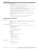
Parts Listings and Cross-Sectional Drawings 372T 408W 761B 408W 113A 408N 382 496 423 333A 408L 361A 370D 497H 332A 497J 112A 497F 497G 370C 134 136 122 400 319 408L Figure 33: STi bearing-frame exploded view 408W 761B 372T 113A 408W 408N 408M 319 168A 370D 423 370B 496 497F 408L 400 361A 332A 497G 370C 134 136 382 122 408A 370E 112A 241 Figure 34: MTi bearing-frame exploded view The finned-tube oil cooler is standard on HT 3196 and optional on all other model
Parts Listings and Cross-Sectional Drawings 555C 555B 551D 494 555B 555C Figure 35: Finned-tube oil cooler exploded view 114 Model 3198 i-FRAME Installation, Operation, and Maintenance Manual
Certification: CE or CE ATEX Certification: CE or CE ATEX Certificates of conformance CSA Certificate Model 3198 i-FRAME Installation, Operation, and Maintenance Manual 115
Certification: CE or CE ATEX 116 Model 3198 i-FRAME Installation, Operation, and Maintenance Manual
Certification: CE or CE ATEX ATEX notification Model 3198 i-FRAME Installation, Operation, and Maintenance Manual 117
Certification: CE or CE ATEX IECEx Certificate of Conformity 118 Model 3198 i-FRAME Installation, Operation, and Maintenance Manual
Certification: CE or CE ATEX Model 3198 i-FRAME Installation, Operation, and Maintenance Manual 119
Certification: CE or CE ATEX Chinese Certificate of Conformity 120 Model 3198 i-FRAME Installation, Operation, and Maintenance Manual
Other Relevant Documentation or Manuals Other Relevant Documentation or Manuals For additional documentation For any other relevant documentation or manuals, contact your ITT representative.
Local ITT Contacts Local ITT Contacts Regional offices Region Address North America (Headquarters) ITT - Goulds Pumps 240 Fall Street Seneca Falls, NY 13148 USA Telephone +1–315–568–2811 Fax +1–315–568–2418 Asia Pacific ITT Industrial Process 10 Jalan Kilang #06-01 Singapore 159410 +65–627–63693 +65– 627–63685 Europe ITT - Goulds Pumps Millwey Rise Industrial Estate Axminster, Devon, England EX13 5HU +44–1297–630250 +44–1297–630256 Latin America ITT - Goulds Pumps Camino La Colina # 1448 Condom
How did we measure up? It is our sincere intention to exceed our customer’s expectations on every order. Tell us if we achieved our goal on your order. Please take our customer satisfaction survey online at: www.ittindustrialproducts.com/feedbacksurvey.html We appreciate you taking the time to provide your feedback. Thank you for buying ITT pumps, parts, and controls.