
User Manual


Guideline Explanation
Make sure that the hold-down bolts for the driver feet are
loose before you make alignment corrections.
This makes it possible to move the
driver when you make alignment
corrections.
Check the alignment again after any mechanical adjustments. This corrects any misalignments that an
adjustment may have caused.
Attach the dial indicators for alignment
You must have two dial indicators in order to complete this procedure.
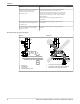
1. Attach two dial indicators on the pump coupling half (X):
a) Attach one indicator (P) so that the indicator rod comes into contact with the perimeter of the
driver coupling half (Y).
This indicator is used to measure parallel misalignment.
b) Attach the other indicator (A) so that the indicator rod comes into contact with the inner end of
the driver coupling half.
This indicator is used to measure angular misalignment.
P
A
Y
X
2. Rotate the pump coupling half (X) in order to check that the indicators are in contact with the driver
coupling half (Y) but do not bottom out.
3. Adjust the indicators if necessary.
Pump-to-driver alignment instructions
Perform angular alignment for a vertical correction
1. Set the angular alignment indicator to zero at the top-center position (12 o’clock) of the driver
coupling half (Y).
2. Rotate the indicator to the bottom-center position (6 o’clock).
3. Record the indicator reading.
When the
reading value
is...
Then...
Negative The coupling halves are farther apart at the bottom than at the top. Perform one of
these steps:
• Add shims in order to raise the feet of the driver at the shaft end.
• Remove shims in order to lower the feet of the driver at the other end.
Positive The coupling halves are closer at the bottom than at the top. Perform one of these
steps:
• Remove shims in order to lower the feet of the driver at the shaft end.
• Add shims in order to raise the feet of the driver at the other end.
Installation
Model 3198 i-FRAME Installation, Operation, and Maintenance Manual 29