
User Manual


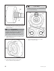


SILICON CARBIDE BEARINGS
(117A-D)
Sleeve Bearings
1. Inspect bearings for cracks and chips.
2. Inspect dimensions per Table 11.
Table 11
Bearing Clearances
Group Location
New Clearance
in. (mm)
Replace
at
in. (mm)
M
Shaft to Bearing
.0045 - .0065
(.114 - .165)
.0085
(.216)
Bearing to
Bearing
.003 - .006
(.076 - .152)
.008
(.203)
Bearing to
Adapter
.0015 - .0035
(.038 - .089)
.0055
(.140)
Thrust Bearings (237)
1. Inspect for cracks or chips.
CONTAINMENT SHELL (750)
1. Wall thickness .050 in. (1.3 mm) minimum.
2. Must be free from pitting or cracks.
3. Grooves in excess of .005 in. (.13 mm) require
containment shell replacement.
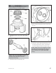
MAGNETS (740A & B)
Driven Magnet Assembly (740A)
s
! WARNING
The magnets contained in this unit are extremely
powerful. Keep magnetic drive components and
magnetic tools apart from each other by a
minimum of six (6) feet [two (2) meters]. Serious
injury to fingers and hands will result otherwise.
1. Must be free from bulges.
2. Must be free of pits and scratches exceeding .005
in. (.13 mm) deep.
3. Must be free of erosion or corrosion exceeding
.005 in. (.13 mm) deep.
4. Inspect wear ring clearance per wear ring
clearance Table 9.
5. Check pump-out vanes for cracks or corrosion.
6. Ensure circulation holes are open.
Drive Magnet Assembly (740B)
s
! WARNING
The magnets contained in this unit are extremely
powerful. Keep magnetic drive components and
magnetic tools apart from each other by a
minimum of six (6) feet [two (2) meters]. Serious
injury to fingers and hands will result otherwise.
NOTE: The magnets are extremely brittle. It is
normal to have chips (up to 10% of the magnet
surface) per MMPA standard no. 0100-90.
1. Magnets must be free of major cracks (extending
over 50% of surface) and also free of
imperfections that create loose particles.
2. If magnets and drive magnet carrier were exposed
to product, they should be replaced.
3. Inspect drive magnet carrier for cracks and replace
if any are found.
4. Drive magnet carrier hub O.D. must be free from
grooves and scratches greater than .005 in. (.13
mm).
5. Inspect magnets for proper bonding to metal
carrier.
BEARING FRAME (228)
1. Visually inspect frame and frame foot for cracks.
2. Inspect for corrosion or pitting if frame has been
exposed to pumpage
3. Inspect frame bearing bores. The maximum
acceptable bore is 3.1506 in. (80.025 mm).
4. Inspect ball bearings for contamination and
damage.
5. Make sure gasket surfaces are clean.
6. Visually inspect bearing end cover (109A) for
cracks and pits. Gasket surface must be clean.
7. Inspect labyrinth seal O-rings (332A) for cuts and
cracks.
8. Replace lip seal.
38 3296 M Group 6/05