
Owner's manual


Maintenance
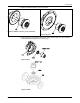
15. Install the impeller assembly and backplate/clamp ring/containment shell assembly into the
casing (100) using casing bolts (372V). Make sure that the O-ring remains in place.
Figure 57: SP3298
16. Set the partially-built assembly aside and away from any attracting metals.
Continue the assembly with the close coupled or frame mounted version of assembly as
described in this chapter.
Reassemble the close-coupled pump
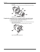
1. Install four expansion plugs (408Z) into the C-face motor support (228) by tapping on the
plug with a 5/8 in. rod.
Expansion plugs are not used for the 182TC - 256TC and 324TSC motor frames.
Figure 58: Close coupled frame
2. Set the C-face motor support (228) on the motor and install four screws (371).
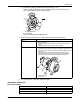
3. Slide the key (178Y) into the motor shaft keyway.
4. Install two setscrews (222L) into the magnet assembly (740B).
Figure 59: Drive magnet
72 3298 Family Installation, Operation, and Maintenance Manual