
Instruction Manual


LEVEL BASEPLATE
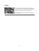
1. Place two sets of wedges or shims on the foundation,
one set on each side of every foundation bolt. The
wedges should extend 20 mm (.75 in.) to 40 mm (1.5
in.) above foundation, to allow for adequate grouting.
This will provide even support for the baseplate once
it is grouted (Fig. 9 and Fig. 10).
2. Remove water and/or debris from anchor bolt
holes/sleeves prior to grouting. If the sleeve type
bolts are being used, fill the sleeves with rags to
prevent grout from entering.
3. Carefully lower baseplate onto foundation bolts.
4. Level baseplate to within 3.2 mm (.125in.) over
length of the baseplate and to within 1.5 mm (.060
in.) over the width of the base by adjusting wedges.
5. Hand tighten bolts.
ALIGNMENT AND ALIGNMENT PROCEDURE
p
! WARNING
Before beginning any alignment procedure, make sure
driver power is locked out.
The points at which alignment is checked and adjusted
are:
·
Initial Alignment is done prior to operation when the
mixer and the driver are at ambient temperature
·
Final Alignment is done after operation when the
mixer and driver are at operating temperature
Alignment is achieved by adding or removing shims from
under the feet of the driver and shifting equipment
horizontally as needed.
NOTE: Proper alignment is the responsibility of the
installer and user of the unit.
Accurate alignment of the equipment must be attained.
Trouble-free operation can be accomplished by following
these procedures.
ALIGNMENT CHECKS
Initial Alignment (Cold Alignment)
·
Before Grouting Baseplate - To ensure alignment can
be obtained
·
After Grouting Baseplate - To ensure no changes have
occurred during grouting process
·
After Connecting Piping - To ensure pipe strains
haven’t altered alignment. If changes have occurred,
alter piping to remove pipe strains on mixer flanges
Final Alignment (Hot Alignment)
·
After First Run - To obtain correct alignment when both
mixer and driver are at operating temperature. Thereafter,
alignment should be checked periodically in accordance
with plant operating procedures.
14
3501 IOM 11/10
Fig. 9
Fig. 10