
Instruction Manual


MAINTENANCE OF SHAFT SEALS
MECHANICAL SEALS
Separate seal manufacturer’s drawings are included with
the mixer data package. Seals are installed and adjusted at
the factory. Manufacturer’s drawings should be filed for
future use in maintaining seal and in adjusting seal when
mixer is disassembled. To properly prepare seal for
operation, various cooling and flushing lines may have to
be connected. Connect cooling and flushing lines to seal as
directed in manufacturer’s instructions.
Mixers with cartridge mechanical seals utilize the
TaperBore™ PLUS seal chamber arrangement. The
TaperBore™ PLUS, in conjunction with a cartridge seal,
simplifies installation and setting
of seals.
The life of a mechanical seal depends on various factors
such as cleanliness of the liquid handled and its
lubricating properties. Due to the diversity of operating
conditions it is, however, not possible to give definite
indications as to its life.
p
! WARNING
Never operate the mixer without liquid supplied to
mechanical seal. Running a mechanical seal dry,
even for a few seconds, can cause seal damage and
must be avoided. Physical injury can occur if
mechanical seal fails.
NOTE: For pumps supplied with cartridge
mechanical seals, be sure the set screws in the seal
locking ring have been tightened and the centering
clips removed prior to startup. Failure to take these
steps could result in damage to the mechanical seal or
shaft sleeve.
ROTOR AXIAL CLEARANCE SETTING
p
! WARNING
Lock out driver power to prevent accidental start-up
and physical injury.
NOTE: For pumps or back pull-out assemblies
supplied with cartridge mechanical seals, the
centering tabs must be in place and tightened, and the
set screw collar loosened. Failure to take these steps
could result in damage to the mechanical seal or
shaft sleeve.
A change in mixer performance may be noted over time by
a decrease in brightness. Performance can usually be
renewed by adjusting the rotor clearance. The total axial
adjustment of the rotor between the casing and the seal
chamber is approximately 5 mm (0.200 in). The rotor
should be centered in the casing.
DIAL INDICATOR METHOD
1. Remove coupling guard.
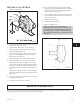
2. Set indicator so that the button contacts either the
shaft end or the face of the coupling (Fig. 23).
3. Loosen jam nuts (423B) on jack bolts (370D) and
back bolts out about two turns.
4. Tighten each locking bolt (370C) evenly, drawing
the bearing housing (134A) towards the bearing
frame (228) until the rotating assembly bottoms out.
5. Set indicator to zero and back locking bolt (370C)
out several turns.
6. Thread adjuster bolts (370D) in until they contact the
bearing frame (228) evenly. Tighten the jack bolts
evenly (about one flat at a time), backing the bearing
housing (134A) away from the bearing frame until
the rotating assembly contacts the seal chamber cover
(184).
7. Record reading on dial indicator.
8. Divide "Total Travel" reading (determined in the
previous step) by 2 and adjust the dial indicator to
that number.
9. Loosen jack bolts (371A) several turns.
10. Tighten locking bolts (370C) evenly until dial
indicator reading is "0".
11. Evenly tighten jack bolts (371A), then locking bolts
(370C), keeping indicator reading at "0".
12. Tighten jam nuts (423B).
13. Check shaft for free turning.
14. Replace coupling guard.
28
3501 IOM 5/10