
Instruction Manual


FEELER GAUGE METHOD
1. Remove coupling guard.
2. Loosen jam nuts (423B) on adjuster bolts (371A) and
back bolts out about two turns.
3. Tighten locking bolts (370C) evenly, drawing
bearing housing (134A) towards frame (228) until
rotating assembly bottoms out.
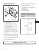
4. With a set of feeler gauges, measure and record the
gap between the bearing housing (134A) and the
bearing frame (228) (Fig. 24).
5. Back locking bolts (370C) off a couple of turns.
6. Thread jack bolts (371A) in until they contact the
bearing frame (228) evenly. Tighten the jack bolts
evenly (about one flat at a time), backing the bearing
housing (134A) away from the bearing frame until
the rotating assembly contacts the seal chamber cover
(184).
7. Using the feeler gauges, measure and record the gap
between the bearing housing (134A) and the bearing
frame (228).
8. Average the two gap measurements and set the feeler
gauge stack to that number.
9. Loosen jack bolts (371A) several turns.
10. Insert feeler gauge stack into gap between bearing
housing (134A) and bearing frame (228). Tighten the
locking bolts (370C) evenly until bearing housing
contacts the feeler gauge stack.
11. Evenly tighten jack bolts (371A), then locking bolts
(370C) while assuring that the feeler gauge does not
bind or become loose.
12. Tighten jam nuts (423B).
13. Check shaft for free turning.
14. Replace coupling guard.
NOTE: For pumps supplied with cartridge
mechanical seals, be sure the set screws in the seal
locking ring have been tightened and the centering
clips removed prior to startup. Failure to take these
steps could result in damage to the mechanical seal or
shaft sleeve.
MIXER WASHDOWN
These mixers are designed to prevent liquid from entering the bearing frame. Care should be taken, however, to avoid
spraying a high pressure stream directly at the labyrinth frame seals.
3501 IOM 11/10 29
5
Fig. 24
Fig. 23