
Instruction Manual


DISASSEMBLY
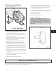
1. Place sling from hoist around bearing frame (228)
(Fig. 26).
2. Remove bearing frame foot hold-down bolts.
3. Remove six (6) casing bolts (370A, casing- to-seal
chamber) and eight (8) casing bolts (469Z,
frame-to-seal chamber to casing) (Fig. 26).
4. Use jack bolts (418) to remove the back pullout.
REMOVAL OF ROTOR
1. Secure back pullout firmly to bench.
2. Lock shaft (122) to prevent turning and remove rotor
nut set screws (222S), rotor nut, and O-ring (Fig. 27).
3. Pry rotor (101) off shaft (182) using two bars
opposite each other, placed between cover and rotor
shroud. Another method of removing the rotor is
using a rotor puller (Fig. 28).
p
! WARNING
Do not use heat on the rotor to help remove, severe
bodily injury could occur.
p
! CAUTION
In order to prevent rotor damage, use pry points
under rotor vanes.
REMOVAL OF TAPERBORE™ PLUS
SEAL CHAMBER AND
MECHANICAL SEAL
1. Re-engage mechanical seal setting clips (Fig. 29).
32
3501 IOM 11/10
Fig. 26
Fig. 28
Fig. 27
Fig. 29