
Instruction Manual


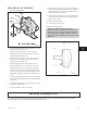


2. Thread a 10 mm eye bolt into the tapped hole
provided in the seal chamber (184) and sling to a
hoist (Fig. 30).
3. Remove the two (2) hex head bolts (370B) from the
seal chamber (184) (Fig. 30).
4. Gently tap the seal chamber (184) with cartridge seal
and mixer sleeve from the frame (228) using a soft
blow hammer on the dry side of the cover (Fig. 30).
5. Remove the four (4) hex nuts (355) and washers
(354) from the seal gland plate.
6. Loosen the set screws on the seal drive collar and
slide the mixer sleeve (126) out of the seal.
7. Service per the seal manufacturer’s instructions.
p
! WARNING
Seal chambers are heavy. Use proper support to
avoid personal injury.
DISASSEMBLY OF BEARING
FRAME
1. Secure bearing frame assembly firmly to a work
bench.
2. Remove coupling hub from shaft (122) by loosening
set screw (if provided) and using a puller (Fig. 31).
3. Remove shaft key (400) (Fig. 31).
4. Remove coupling guard end plate by removing
bearing housing adjuster screws (370C) (Fig. 31).
5. Remove labyrinth shaft seal assemblies (332A,
333A) from each end of frame (Fig. 31).
6. Slide rotating element out of frame (228). If needed,
tap rotor end of shaft with a soft blow hammer to
assist in removal (Fig. 32).
p
! WARNING
Support both ends of shaft to prevent rotating
element from dropping when bearings are disen-
gaged from bores.
7. Radial end cover (109A) is installed permanently at
factory and should not require removal.
8. Remove thrust bearing retainer ring (253B) by
removing socket head cap screws (236A) (Fig. 33).
9. Slide thrust bearing housing (134A) off thrust
bearings (112) (Fig. 33).
3501 IOM 11/10 33
Fig. 30
Fig. 31
Fig. 32
Fig. 33
6