
Instruction Manual


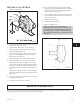


10. Disengage thrust bearing lock washer (382) from
locknut (136) and remove both from shaft (122)
(Fig 34).
11. Remove bearings (112, 409) from shaft (122) using a
suitable puller that only contacts inner races of
bearings (Fig. 34).
INSPECTIONS
CASING
1. Thoroughly clean gasket surfaces and alignment fits
to remove rust and debris.
2. Inspect for any unusual erosive wear inside casing.
ROTOR
1. Inspect leading and trailing edges of vanes for
pitting, and erosion or corrosion damage.
2. Inspect keyway and bores for damage.
SEAL CHAMBER
1. Thoroughly clean gasket surfaces and fits to remove
rust and debris.
2. Inspect surface for pitting, and erosion or corrosion
damage.
BEARING FRAME
1. Inspect frame and frame foot for cracks.
2. Inspect for corrosion or pitting if frame has been
exposed to the fluid.
3. Inspect frame bearing bores per Table 7.
4. Inspect labyrinth seal o-rings for cuts and cracks.
5. Inspect shafts and sleeves for wear.
34
3501 IOM 11/10
Fig. 34
Table 7
Bearing Frame
GROUP BEARING
Maximum Bearing Frame (228) Bore
mm(inch)
Maximum Bearing Housing (134A) Bore
mm (inch)
M
Thrust
Radial
160.02 (6.3002)
130.03 (5.1191)
130.03 (5.1191)
L
Thrust
Radial
200.15 (7.8752)
150.11 (5.9065)
160.02 (6.3002)
XL
Thrust
Radial
240.03 (9.4500)
180.09 (7.0876)
189.99 (7.4815)
Table 8
Bearing Sizes
GROUP THRUST BEARING RADIAL BEARING
M 7312BECBY NUP312ECP
L 7315BECBY NUP314ECP
XL 7318BECBY NUP317ECP