
Instruction Manual


·
two on right side (at coupling end)
·
one on left side
·
one on top at seal chamber end
b. Install oil sight glass (319) on right side of
bearing frame (228) as viewed from coupling
end.
c. Install oil drain plug (408B) into bottom of
bearing frame (228).
d. If equipped with a sight oiler (251), install on
left side of bearing frame (228) as viewed from
coupling end.
Grease Lubrication
a. Install two grease fittings (193H) into bearing
frame (228) as follows, based on viewing from
coupling end (Fig. 43):
·
one on left side at coupling end
·
one on top at seal chamber end.
b. Install two plugs (408C) into right side of
bearing frame (228), based on viewing from
coupling end.
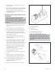
c. Install oil drain plug (408B) into bottom of
bearing frame (228) (Fig. 42).
27. If equipped with an oil cooler, install cooler
assembly into bearing frame (228), based on viewing
from coupling end as follows (Fig. 44):
a. Install one tube fitting with straight bore on left
side of frame.
b. Slide finned tube through the hole on right side
of frame.
c. Install reducer bushing on right side of frame .
d. Thread a second tube fitting (with straight bore)
into reducer bushing.
e. Center tube in frame and tighten ferrule nuts on
tube fittings.
f. Install one tube fitting with a stepped bore
on each end of tube and tighten ferrule nuts.
REASSEMBLY OF TAPERBORE™
PLUS SEAL CHAMBER AND
MECHANICAL SEAL
1. Apply a liberal amount of an anti-galling compound
(Loctite “Nickel Anti-seize”) to shaft sleeve (126)
bore and shaft (122) (Fig. 45).
2. Slide sleeve (126) onto shaft (122).
3. Completely lubricate the O-ring in the bore of the
mechanical seal sleeve.
38
3501 IOM 11/10
Fig. 43
Fig. 42
408B
Fig. 44
Fig. 45