
Instruction Manual


4. Install cartridge seal on sleeve (126).
5. Rig lifting device to eyebolt in seal chamber (184) and
install seal chamber (184) on bearing frame (228).
6. Install hex head bolts (370B).
7. Slide cartridge seal on gland studs (353). Assure that
gland studs align with openings in gland, and that the
tap connections are in the correct orientation.
8. Install gland stud washers (354) and nuts (355) and
finger tighten the gland nuts. Do not tighten the nuts
or set seal until after the mixer rotor is adjusted.
9. After the rotor is installed and clearance is set, secure
the mechanical seal as follows:
a. Refer to mechanical seal drawing.
b. Tighten gland nuts (355) evenly.
c. Tighten set screws in drive collar while setting
clips are engaged.
d. Remove setting clips.
INSTALLATION OF ROTOR
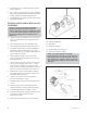
1. Install shaft key (178) on shaft (122) (Fig. 46).
2. Fit sleeve O-ring (412F) into groove on shaft sleeve
(126).
3. Apply a liberal coating of an anti-galling compound
(Loctite “Nickel Anti-seize”) to mixer rotor (101)
bore and shaft (122).
4. Slide mixer rotor (101) onto shaft (122). Ensure
sleeve O-ring (412F) stays in groove.
5. Fit rotor nut O-ring (412A) into groove in rotor nut
(304).
6. Degrease rotor nut (304) and shaft (122) threads and
apply ND Industries VIBRA-TITE Formula 3 thread
sealing compound to threads in nut.
7. Install rotor nut (304) on shaft (122).
8. Prevent coupling end of shaft from turning and
torque rotor nut to specified amount on Table 9.
p
!
CAUTION
Failure to torque rotor nut can result in serious
mechanical damage.
9. Apply ND Industries VIBRA-TITE Formula 3 thread
sealing compound to rotor nut set screws (222S).
10. Install and tighten rotor nut set screws (222S).
INSTALLATION OF CASING FOOT
AND ALIGNMENT PIN
NOTE: Model 3501 6" and 8" mixers require a
casing foot (131). The 12" mixer does not. Model
3501 8" mixers require an alignment pin on the inlet
flange to ensure that the chemical injection pipe (174)
is properly oriented. The 6" and 12" mixers do not
require the alignment pin.
p
! WARNING
Mixer components are heavy. Proper methods of
lifting and securing must be employed to avoid
physical injury and/or equipment damage.
1. For 6" and 8" mixers, determine the correct
orientation of the casing from the order documents.
Model 3501 6" and 8" mixers have a transverse
stationary vane in the casing (100) which must be
oriented toward the chemical injection pipe (174).
The 12" mixer does not (Fig. 46A).
2. Align holes in casing foot (131) with tapped holes on
appropriate casing (100) foot bosses. These are
normally the holes facing the baseplate.
3501 IOM 11/10 39
6
Fig. 46
Fig. 46A