
Instruction Manual


3. Install hex cap screws (370F) and tighten to torque
value in Table A-1.
4. For 8" mixers, degrease threads in casing (100) inlet
flange, and apply ND Industries VIBRA-TITE thread
sealing compound to threads on alignment pin.
5. Install alignment pin (shank plug) into tapped hole in
inlet flange and tighten.
INSTALLATION OF BACK PULL-OUT
ASSEMBLY
NOTE: For pumps or back pull-out assemblies
supplied with cartridge mechanical seals, the
centering tabs must be in place and tightened, and the
set screw collar loosened. Failure to take these steps
could result in damage to the mechanical seal or
shaft sleeve.
1. Adjust rotor (101) so gap between rear rotor shroud
vanes and seal chamber (184) is approximately 0.5
mm (.02 in.).
2. Place casing gasket (351) on seal chamber (184).
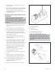
3. Place sling from hoist around frame (228) (Fig. 47).
4. On a flat surface (baseplate or sturdy workbench),
install back pull-out assembly into casing (100).
Ensure casing foot (131), if supplied, and frame foot
(241) are flat on the surface.
5. Hand tighten four equally spaced casing bolts
(370A). Seat back pull-out into casing (100) - Do
not tighten bolts yet.
6. Check total travel of rotor in casing. Assuming new
parts are used, acceptable values are 3.3 - 5.8 mm
(0.130-0.230 in.) of total travel. If outside of this
range, worn parts, improper installation or too much
pipe strain is present. Determine cause and correct.
7. If total travel is within criteria, tighten remaining
casing bolts and torque to specified value in a cross
bolt pattern.(Refer to Table 9).
8. Set rotor (101) axial clearance as described in
Preventive Maintenance section.
9. Install and tighten casing foot nut to baseplate bolts
(372V)
10. Determine gap, if any, between frame foot and
baseplate with feeler gauges and shim accordingly.
11. Install and tighten frame to baseplate (372W)
12. Lubricate bearing frame assembly with oil or grease
as described in Operation and Preventive
Maintenance sections.
13. Rotate shaft (122) by hand to assure free rotation.
14. Reinstall coupling hub.
15. Align mixer.
16. Reconnect coupling.
17. Install coupling guard (Fig. 48).
18. Reconnect all auxiliary piping.
NOTE: For pumps supplied with cartridge
mechanical seals, be sure the set screws in the seal
locking ring have been tightened and the centering
clips removed prior to startup. Failure to take these
steps could result in damage to the mechanical seal or
shaft sleeve.
40
3501 IOM 11/10
Fig. 47
Fig. 48