Installation, Operation and Maintenance Manual Series E1 / E3 Instant hot water recirculating systems
en – Original Instructions Table of Contents 1 2 3 4 Introduction and Safety ............................................................................................................................................ 4 1.1 Introduction ...................................................................................................................................................... 4 1.2 Safety .......................................................................................................
en – Original Instructions 5.6.1 Fix speed models ....................................................................................................................................... 33 5.6.2 Variable speed models .............................................................................................................................. 33 5.6.3 Fix speed models with fix value temperature control .............................................................................. 33 5.6.
en – Original Instructions 1 Introduction and Safety 1.1 Introduction Purpose of this manual This manual provides information on how to do the following in the correct manner: • Installation • Operation • Maintenance CAUTION: This manual is an integral part of the unit. Make sure to have read and understood the manual before installing the unit and putting it to use.
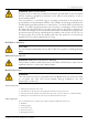
en – Original Instructions Danger levels Hazard level Indication DANGER: It identifies a dangerous situation which, if not avoided, causes serious injury, or even death. WARNING: It identifies a dangerous situation which, if not avoided, may cause serious injury, or even death. CAUTION: It identifies a dangerous situation which, if not avoided, may cause small or medium level injuries. NOTICE: It identifies a situation which, if not avoided, may cause damage to property but not to people.
en – Original Instructions 1.2.2 User Safety IMPORTANT SAFETY INSTRUCTIONS CAUTION: When installing and using this equipment, basic safety precautions should always be followed. Read, follow and save all these instructions! WARNING: To reduce the risk of injury, do not permit children to use this product unless they are closely supervised at all times.
en – Original Instructions WARNING: Risk of electric shock Connect only to a branch circuit protected by a ground-fault circuit-interrupter (GFCI). Contact a qualified electrician if you cannot verify that the circuit is protected by a GFCI. The unit must be connected only to a supply circuit that is protected by a ground-fault circuit-interrupter (GFCI). Such a GFCI should be provided by the installer and should be tested on a routine basis. To test the GFCI, push the test button.
en – Original Instructions Electrical connections Electrical connections must be made by certified electricians in compliance with all international, national, state, and local regulations. Precautions before work Observe these safety precautions before you work with the product: • Make sure that you have a clear path of retreat. • Allow all system and pump components to cool before you handle them. • Make sure that the product has been thoroughly cleaned.
en – Original Instructions 2 Handling and Storage 2.1 Handling of the packed unit WARNING: Take appropriate measures during transport, installation and storage to prevent contamination from external substances. The Manufacturer delivers the unit and its components in a cardboard box. 2.2 Unit inspection upon delivery 2.2.1 Inspect the package 1. Check that quantity, descriptions and product codes match the order. 2. Check the packaging for any damage or missing components. 3.
en – Original Instructions 2.3 Unit handling WARNING: Electrical hazard Holding the unit by the supply cord is strictly forbidden. WARNING: During handling, make sure to avoid injury to people and animals, and/or damage to property. 2.
en – Original Instructions 3 Technical Description 3.1 Designation Domestic hot water circulating pump. OEM applications For special OEM applications the pump has customized versions, which differ from the standard versions in one or more features of the followings: • Special software functions • Customized power supply cable (special connectors or terminals) • Alternative circulating fluid • Built-in applications (water pumps for use in water heaters, spas, etc.) 3.
en – Original Instructions 3.3 Data plate Figure 1 No. 1 2 3 4 5 6 3.4 Description Applied UL standard Rated voltage Frequency Input power Serial number incl. manufacturing date Part number No. 7 8 9 10 Description Technical code Nominal system pressure Maximum water temperature 11 Model description Maximum water temperature for using with drinking water (NSF 61 classified) Model description Figure 2 No. * 12 Description Notes E1 = Max. speed: 3600 rpm 1 Series model name E3 = Max.
en – Original Instructions 3.5 Names of the main components and accessories Figure 3 No. Description No. Description 1 End cap 12 Pump housing Autocirc (code: BCA) 2 Control knob 13 Fixing bracket 3 Stator (pump motor) 14 Screw 5/32”x1 9/16” (4x40 mm); 2 pcs. 4 Cable gland 15 5 Screw ring Plastic anchor 1/4”x1 3/16” (6x30 mm); 2 pcs. 6 Ceramic bearing ball 16 Pump housing Sweat (code: BCS) 7 O-ring 17 Union fitting for 1/2” copper pipe; 2 pcs.
en – Original Instructions 3.6 Intended use Circulating pump for domestic hot water systems. If hot water is not used for longer periods of time, the water in the hot water pipe cools off. Domestic hot water pumps (also called sanitary or drinking water circulating pumps) pump this cold water back into the water heater via a separate recirculation pipe, or directly into the cold water supply line (see Figure 5 and Figure 6 on page 19 and 20).
en – Original Instructions Figure 4 No. Description No. Description 1 Pump inlet from hot water supply line 3 Pump outlet to faucet/tap for cold water 2 Pump outlet to faucet/tap for hot water 4 Pump inlet from cold water supply line Pumped liquids CAUTION: This pump has been designed and tested for use with water only. Its suitability for use with liquids other than water is the end user's responsibility.
en – Original Instructions 3.7 Improper use WARNING: The unit was designed and built for the use described in section 3.6 Intended use on page 14. Any other uses are prohibited, as they could compromise the safety of the user and the efficiency of the unit itself. DANGER: It is prohibited to use this unit to pump flammable and/or explosive liquids. CAUTION: It is prohibited to use the unit to pump aggressive liquids, acids and seawater.
en – Original Instructions 4 Installation 4.1 Precautions Before starting, make sure that the safety instructions shown in section 1.2 Safety on page 4 have been fully read and understood. DANGER: Potentially explosive atmosphere hazard It is prohibited to start the unit in environments with potentially explosive atmospheres or with combustible dusts. WARNING: Always wear personal protective equipment. WARNING: Always use suitable working tools.
en – Original Instructions 4.3 Hydraulic connection WARNING: All the hydraulic connections must be completed by a technician possessing the technicalprofessional requirements outlined in the current regulations. WARNING: Excessive system pressure hazard Piping must be sized to ensure safety at the maximum operating pressure. The maximum pressure value of the pump is listed on the data plate. Do not exceed this pressure.
en – Original Instructions • We recommend, that for pump models with pump housing code BCT or BCS, you install a ball shut-off valve before the pump at least, for future maintenance or repair works. • A properly installed system should include a method of automatically venting the air that enters the water supply line during use. Air enters the system each time fresh, cold water is introduced into the hot water heater.
en – Original Instructions Figure 6 No. Description No. Description 1 Tee fitting 5 Circulating pump model BCU 2 Hot water return (recirculation) line 6 Hose bib 3 Hot water supply line 7 Water heater 4 Cold water supply line 8 “Y” fitting Autocirc pumps • Select the sink under which the Autocirc pump is to be located (the sink where the hot water takes longest to arrive, which is usually the sink farthest from the water heater).
en – Original Instructions • Before starting installation work close the under sink hot and cold water riser shut-off valves and open the hot and cold water faucets/taps to relieve the water pressure. Close the water faucets/taps. NOTICE: In some older homes, the riser shut-off valves may be difficult to shut off completely, or maybe it is necessary to turn the valves into a different orientation. If this is the case shut the water off at the main water inlet valve to the house. Figure 7 No.
en – Original Instructions 4.3.2 Installation WARNING: Danger, system pressurized Before starting work, close the shut-off valves on the suction and discharge sides or drain the system. CAUTION: Install appropriate seals between the unit couplings and the piping system. WARNING: Hot water leakage hazard Pressurize the system slowly while checking for leaks at all joints with gaskets or solder connections.
en – Original Instructions Permitted positions for recirculating pumps Figure 8 Autocirc pumps - Installation sequence 1. First read and follow the concerning instructions in section 4.3.1 Guidelines for the hydraulic system on page 20-21. 2. Fasten the Autocirc unit to the wall under the sink using the wall bracket provided in the Autocirc kit. Be sure the pump timer is turned toward the front and is accessible for setting and changing the time.
en – Original Instructions 3. Remove the existing flexible line connection to the hot and cold water faucet/tap threaded nipples. 4. Screw on the two existing 1/2” hose connections to the corresponding hot and cold sides of the pump housing (see Figure 10). Be sure not to “kink” these existing hose lines during bending which may prevent adequate flow and/or cause the valves to break. If necessary turn the riser shut-off valves into a more favorable orientation.
en – Original Instructions Figure 11 4.3.3 Rotation of the pump motor WARNING: Danger, system pressurized Before starting work, close the shut-off valves on the suction and discharge sides or drain the system. CAUTION: During the loosening of the screw ring from the pump housing, it is possible the leakage of residual very hot or cold liquid: pay attention to the risk of damages to persons.
en – Original Instructions 1. Loosen the screw ring before installation. 2. Rotate the pump motor to the required installation position. 3. Tighten the screw ring. When installing the recirculating pump in a horizontal position, the timer shall point upwards. It may be turned in the range from 10:30 to 13:30 (±45°) at maximum, in order to maintain the ingress protection class (see Figure 13 on page 26).
en – Original Instructions 4.4 Electrical connection WARNING: Risk of electric shock Electrical connections are to be made by a qualified electrician in accordance with all applicable codes, ordinances and good practices. DANGER: Electrical hazard Disconnect and lock out the power before making electrical connections. Before starting work, check that the unit cannot restart, even unintentionally. CAUTION: For supply connection, use wires acceptable for at least 194 °F (90 °C). Use copper conductors only.
en – Original Instructions 4.4.2 Guidelines for electrical connection • Check that the mains voltage and frequency match the specifications on the data plate. • Protect the supply cord from high temperatures, vibrations, collisions and abrasions. • Check that the power supply line is provided with a short circuit protection device of appropriate size. • If the pump unit is supplied with a power cord with grounding-type attachment plug, connect it only to a properly grounded, grounding-type receptacle.
en – Original Instructions 5. Cable installation: • Insert the cable through the threaded hole into the motor housing. • Push the lever of the terminal block with a flat screw driver and get each stripped core into the proper hole. • Take care of matching the markings of the terminal block with the proper cable colors. • The whole stripped conductor length must be inside of the terminal block. • Insert the cable gland components into the housing and tighten the nut. 6.
en – Original Instructions 5 Use and Operation 5.1 Precautions WARNING Make sure that the discharged liquid cannot cause damage to persons or things. WARNING: Electrical hazard Check that the unit is properly connected to the mains power supply. WARNING: Hot surface hazard Motor housing may be very hot. Burn hazard. Do not touch. NOTICE: Dry run of the unit is prohibited, as this can destroy the bearings in a very short time. NOTICE: It is prohibited to operate the unit with the shut-off valve closed.
en – Original Instructions 5.4 Air purge After filling the system with liquid, any residual air shall be removed from the pump housing. To aid this effort, the standard pump models with control knob are equipped with a built-in air purge function. For activation, turn the knob to the right end position for 5 seconds (the air purge symbol is shown on the scale, see Figure 15). A 10 minute long air purging sequence starts, which includes several max and min speed sequences, stoppages.
en – Original Instructions 3. Program the on/off times by pulling the tabs outward until flushing with the dial face for the pump to operate on during selected time periods. Push the tabs inward, one step behind the dial face for the pump to remain off during the selected time periods. Each timer tab covers a 30-minute period. The illustration shows a setting, where the pump is to be in operation between 4 a.m. and 2 p.m. 4.
en – Original Instructions 5.6 Operation modes According to the chart in section 3.2 Integrated features and functions on page 11, the different pump versions have different integrated functions, thus operation modes. 5.6.1 Fix speed models These pumps are not equipped with a control knob; run on a constant speed if energized, until reaching the power limit, then the speed may be reduced. Timer controlled version is available, standby and air purge functions are not available. 5.6.
en – Original Instructions 5.6.5 Autocirc pumps These pumps are the timer controlled versions of the fix speed models with temperature control, equipped with a special pump housing for simple under sink installation. There are two models: • E1-BCAFNCTW: Fix value temperature controlled (for operation details see section 5.6.3 on page 33). • E1-BCAFNRTW: Variable value temperature controlled with adjustable restart temperature (see the second paragraph of section 5.6.4 on page 33).
en – Original Instructions 5.6.8 Dry run protection This function is available only for some fix speed models. This algorithm protects the unit from dry running during normal operation. The pump monitors the input power level and if it drops below a preset value for a specified time interval, the pump starts a sequence with 9 cycles of 30 s on and 60 s off, then a 10-minute pause and so on, until the expected power level restored and the pump can continue the normal operation. 5.6.
en – Original Instructions 6 Maintenance 6.1 Precautions Before starting, make sure that the instructions shown in section 1 Introduction and Safety on page 4 have been fully read and understood. DANGER: Electrical hazard The unit must not be used if the cable or the electrical compartment is damaged. Damaged cable may only be replaced (so that danger is avoided) by the manufacturer, its service agent or a trained professional electrician.
en – Original Instructions 6.3 Autocirc pumps If you are away from home for extended periods of time (2 weeks or more) you may choose to turn the system off (slide the timer switch to the "Off" position) as there is no need to maintain hot water in the supply line when no one is home to enjoy this convenience.
en – Original Instructions 7 Troubleshooting 7.1 Precautions WARNING: Maintenance must be done by a technician possessing the technical-professional requirements outlined in the current regulations. WARNING: Observe the safety requirements in section 5 Use and Operation on page 30 and section 6 Maintenance on page 36. WARNING: If a fault cannot be corrected or is not mentioned, contact Xylem or the Authorized Distributor. 7.
en – Original Instructions 7.5 Noise in the system The pump should be virtually noiseless during operation. The rotor may make a brief but hardly perceptible fluttering noise immediately after the pump is turned off. During normal operation, an occasional air bubble may pass through the pump housing causing a momentary gurgling noise. However, if noise at the pump persists for any prolonged period, correct the problem.
en – Original Instructions 8 Technical Information 8.1 Certifications The pump models covered by this manual are certified generally under the safety standard UL 778, but in case of some special OEM models (usually with plastic pump housing for spa application) the UL 1081 certification is also available. This reference is indicated on the data plate, see item 1 in Figure 1 on page 12. These pumps are also certified as a Drinking Water System Component according to NSF/ANSI 61. 8.
en – Original Instructions 8.5 Mechanical characteristics Ingress protection class Without timer: With timer: IP 44 IP 42 Maximum working pressure UL 778 certified models: 145 psi (1.0 MPa) UL 1081 certified models: 29 psi (0.2 MPa) Sound pressure level ≤ 40 dB(A) 8.6 Dimensions and weights E _ -BCS _ _ _ _ _ E _ -BCT _ _ _ _ _ Models Weight [lb (kg)] E_ -BCSVNNNW E_-BCSF_CNW E_-BCSF_RNW E_-BCSF_NNW 2.2 (1.0) E_-BCSVNNNN E_-BCSF_CNN E_-BCSF_RNN E_-BCSF_NNN 1.8 (0.
en – Original Instructions E _ -BCU _ _ _ _ _ E _ -BCAFN _ TW Models 42 Weight [lb (kg)] E_-BCUVNNNW E_-BCUF_CNW E_-BCUF_RNW E_-BCUF_NNW 2.6 (1.2) E_-BCUVNNNN E_-BCUF_CNN E_-BCUF_RNN E_-BCUF_NNN 2.2 (1.0) E_-BCUVNNTW E_-BCUF_CTW E_-BCUF_RTW E_-BCUF_NTW 2.9 (1.3) E_-BCUVNNTN E_-BCUF_CTN E_-BCUF_RTN E_-BCUF_NTN 2.4 (1.1) — E1-BCAFNCTW E1-BCAFNRTW — 2.9 (1.
en – Original Instructions 8.
en – Original Instructions 44 E3-BCSF_ _ N _ & E3-BCTF_ _ N _ E3-BCSVN _ N _ & E3-BCTVN _ N _ E1-BCAFN _ TW E3-BCUVN _ N _ Installation, Operation and Maintenance Manual
en – Original Instructions 8.8 OEM models For special OEM (Original Equipment Manufacturer) applications the pump has customized versions, which differ from the standard trade versions in some features. An individual PSS (Product Specification Sheet) document is issued for each of these versions including the hydraulic curve and the technical details highlighting the difference from the standard versions.
en – Original Instructions 9 Disposal 9.1 Precautions WARNING: The unit must be disposed of through approved companies specialized in the identification of different types of materials (steel, copper, plastic, etc.). WARNING: It is prohibited to dispose of lubricating fluids and other hazardous substances in the environment. Recycling guidelines Always follow local laws and regulations regarding recycling.
en – Original Instructions 10 Warranty Commercial warranty For goods sold to commercial buyers, Seller warrants the goods sold to Buyer hereunder (with the exception of membranes, seals, gaskets, elastomer materials, coatings and other "wear parts" or consumables all of which are not warranted except as otherwise provided in the quotation or sales form) will be (i) be built in accordance with the specifications referred to in the quotation or sales form, if such specifications are expressly made a part of
en – Original Instructions Limited consumer warranty For goods sold for personal, family or household purposes, Seller warrants the goods purchased hereunder (with the exception of membranes, seals, gaskets, elastomer materials, coatings and other "wear parts" or consumables all of which are not warranted except as otherwise provided in the quotation or sales form) will be free from defects in material and workmanship for a period of twelve (12) from the date of installation or twenty-four (24) months from
Xylem |’zīləm| 1) The tissue in plants that brings water upward from the roots; 2) A leading global water technology company. We’re a global team unified in a common purpose: creating innovative solutions to meet our world’s water needs. Developing new technologies that will improve the way water is used, conserved, and re-used in the future is central to our work.