
Product Manual


4
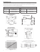
out adapter should locate the pump opposite the influent
opening preventing stagnate areas where solids can settle.
The basin or pit must be capable of supporting the weight
of the pump and guide rail. The pit floor must be flat.
NOTICE: FOLLOW THE INSTRUCTIONS THAT
ARE PROVIDED WITH THE GUIDE RAIL
ASSEMBLY.
PIPING
Discharge piping should be no smaller than the pump
discharge diameter and kept as short as possible, avoiding
unnecessary fittings to minimize friction losses.
Install an adequately sized check valve matched to the
solids handling capability of the pump to prevent fluid
backflow. Backflow can allow the pump to spin back-
wards and may cause premature seal, bearing, shaft wear.
If the pump is turning backwards when it is called on to
start the increased torque may cause damage to the pump
motor and/or motor shaft.
Install an adequately sized gate valve AFTER the check
valve for pump, plumbing and check valve maintenance.
Important – Before pump installation. Drill a
3
⁄
16
”
(4.8mm) relief hole in the discharge pipe. It should be
located within the wetwell, 2” (51mm) above the pump
discharge but below the check valve. The relief hole
allows any air to escape from the casing. Allowing liquid
into the casing will insure that the pump can start when
the liquid level rises. Unless a relief hole is provided, a
bottom intake pump could “air lock” and will not pump
water even though the impeller turns.
All piping must be adequately supported, so as not to
impart any piping strain or loads on the pump.
The pit access cover must be of sufficient size to allow for
inspection, maintenance and crane or hoist service.
WIRING AND GROUNDING
Important notice: Read Safety Instructions before
proceeding with any wiring.
Use only stranded copper wire to pump/motor and
ground. The ground wire must be at least as large
as the power supply wires. Wires should be color
coded for ease of maintenance and troubleshooting.
Install wire and ground according to the National
Electrical Code (NEC), or the Canadian Electrical
Code, as well as all local, state and provincial codes.
Install an all leg disconnect switch where required
by code.
Disconnect and lockout electrical power before
performing any service or installation.
The electrical supply voltage and phase must match
all equipment requirements. Incorrect voltage or
phase can cause fire, motor and control damage,
and voids the warranty.
All splices must be waterproof. If using splice kits
follow manufacturer’s instructions.
Select the correct type and NEMA grade
junction box for the application and lo-
cation. The junction box must insure dry,
safe wiring connections.
Seal all controls from gases present which
may damage electrical components.
FAILURE TO PERMANENTLY
GROUND THE PUMP, MOTOR AND
CONTROLS BEFORE CONNECTING
TO POWER CAN CAUSE SHOCK,
BURNS OR DEATH.
SELECTING AND WIRING
PUMP CONTROL PANELS AND SWITCHES
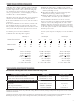
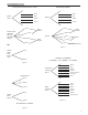
FLOAT SWITCH TYPES
There are two basic float switch designs; single-action
and wide-angle. Single-action switches operate over a
range of 15º so they open and close quickly. Wide-angle
floats operate over a 90º swing with the tether length be-
tween the float body and the pivot point controlling the
On-Off range. The design determines how many floats
are required with different systems or controls.
Floats may be normally open (NO) for pump down
applications or to empty a tank. Normally closed (NC)
switches are used to pump up or to fill a tank.
A single-action control switch may be used only with a
control panel, never direct connected to a pump.
The wide-angle, pump down switches may be used as
direct connected pump switches or as control switches.
SETTING THE FLOAT SWITCHES
There are no absolute rules for where to set the float
switches, it varies from job to job.
Suggested Rules to Follow:
All floats should be set below the Inlet pipe!
Off Float: Best: set so free hanging the water level is
always above the top of the pump (motor dome). Next
Best: set so the water level is not more than 6" below the
top of the pump.
On Float: set so the volume of water between the On and
Off floats allows pumps of 1½ HP and under to operate
for 1 minute minimum. Two (2) HP and larger pumps
should run a minimum of 2 minutes. Basin technical
brochure states the gallons of storage per inch of basin
height.
Lag/Alarm Float(s): should be staggered above the Off
and On floats. Try to use most of the available stor-
age provided by the basin, save some space for reserve
storage capacity. Exact reserve may be called out by local
codes. See Diagrams and Charts in Float Switch Chart
Section.
PANEL WIRING DIAGRAMS
Our control panels are shipped with instructions and wir-
ing diagrams. Use those instructions in conjunction with
this IOM. Electrical installation should be performed
only by qualified technicians. Any problem or questions
pertaining to another brand control must be referred to
that control supplier or manufacturer.
ALARMS
We recommend the installation of an alarm on all Waste-
water pump installations. Many standard control panels
come equipped with alarm circuits. If a control panel is
not used, a stand alone high liquid level alarm is avail-
able. The alarm alerts the owner of a high liquid level
in the basin so they can contact the appropriate service
personnel to investigate the situation.
WARNING
Hazardous
voltage
WARNING
WARNING