
Product Manual


6
Use the pump H-O-A (Hand-Off-Automatic) switches in
Hand to test the pumps. If they operate well in Hand pro-
ceed to test Automatic operation. If the pumps run but fail
to pump, they are probably air locked, drill the relief holes
per the instructions in the Piping Section.
Place Control Panel switch(es) in Automatic position and
thoroughly test the operation of the ON, OFF, and Alarm
floats by filling the wetwell with clear water. Important:
Failure to provide a Neutral from the power supply to a
1Ø, 230 volt Control Panel will not allow the panel control
circuit to operate. The Neutral is necessary to complete the
115 volt control circuit.
Check voltage and amperage and record the data on the
front of this manual for future reference. Compare the am-
perage readings to the pump nameplate maximum amper-
age. If higher than nameplate amperage investigate cause.
Operating the pump off the curve, i.e. with too little head
or with high or low voltage will increase amperage. The
motor will operate properly with voltage not more than
10% above or below pump nameplate ratings. Performance
within this range will not necessarily be the same as the pub-
lished performance at the exact rated nameplate frequency
and voltage. Correct the problem before proceeding. Three
phase unbalance is also a possible cause. See Three Phase
Power Unbalance and follow the instructions.
Reset the Alarm circuit, place pump switch(es) in the Au-
tomatic position and Control Switch in ON position. The
system is now ready for automatic operation.
Explain the operation of the pumps, controls and alarms to
the end user. Leave the paperwork with the owner or at the
control panel if in a dry, secure location.
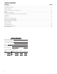
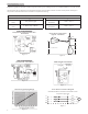
FLOAT SWITCH AND PANEL CHART
The purpose of this chart is to show the required switch
quantities and the function of each switch in a typical
wastewater system. The quantities required vary de-
pending on the switch type, single-action or wide-angle.
Switch quantities also vary by panel type: simplex with
and without alarms, and duplex with alarms.
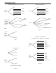
Duplex Panels using single-action switches:
Three Float Panel Wiring
SW1 Bottom Pumps Off
SW2 Middle 1st Pump On
SW3 Top 2nd Pump & Alarm On
Four Float Panel Wiring ➁
SW1 Bottom Pumps Off
SW2 2nd 1st Pump On
SW3 3rd 2nd Pump On
SW4 Top Alarm On
Duplex Panels using wide-angle switches:
Three Float Panel Wiring
SW1 Bottom 1st Pump On/Both Off
SW2 Top 2nd Pump & Alarm On
Four Float Panel Wiring
SW1 Bottom 1st Pump On/Both Off
SW2 Middle 2nd Pump On
SW3 Top Alarm On
Simplex Panel using single-action switches:
Simplex Panel with Alarm ①
SW1 Bottom Pump Off
SW2 Middle Pump On
SW3 Top Alarm On/Off
Simplex Panel with No Alarm
SW1 Bottom Pump Off
SW2 Top Pump On
Inlet
Alarm SW3
Pump On SW2
Pump Off SW1
Discharge
Inlet
Alarm SW4
Lag Pump On
SW3
Pump Off
SW1
Discharge
Lead Pump On
SW2
Simplex ①
Duplex ➁
Simplex Panel using wide-angle switches:
Simplex Panel with Alarm
SW1 Bottom Pump On/Off
SW2 Top Alarm On/Off
Simplex Panel with No Alarm
SW1 Pump On/Off