
User's Manual


2. INSTALLATION
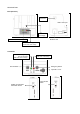
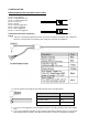
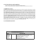
PIN DESCRIPTION OF THE BASE OUTPUT PORT
Connector wire (RJ45)
Pin #1 : Transmitter Audio out
Pin #2 : In Car Mic. Audio out
Pin #3 : 12V DC_IN
Pin #4 : Ground
Pin #5 : Record Trigger OUT
Pin #6 : Record Trigger IN
Pin #7 : Panic Trigger Out
Pin #8 : In Car Mic. Trigger IN
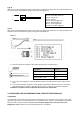
Terminated Connector ( Optional )
Type A
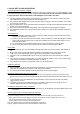
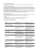
1) Wire the un-terminated signal wires to the control unit according to the signal chart. 5 Amp fast
blow fuse is recommend in the 12VDC power supply line to protect the equipment.
2) Plug the 3.5mm stereo plug into the audio input jack of the recording device.
3) If it is to be used, plug in the in-car microphone into the In-Car Mic jack in the side of the receiver
base.
4) Turn on the transmitter and place it in the charging cradle with the beltclip facing out. The Charge
LED will light if there is power. If the LEDs do not come on, check the connections and repeat.
Description Position
Audio Ground Sleeve
Transmitter Audio Ring
Inside Car Mic. Audio Tip
8
1
8
1