
Product Manual


3Rev. D 921422-18
If you require a greater initial prime height, coat the
gears with uid by removing the plug on the top of the
pump and pour a small quantity of motor oil into the gear
cavity. Replace the plug and try again. A foot valve with
pressure relief may be needed to maintain prime.
Make sure all threaded fuel connections are wrapped
with three to four turns of thread tape or a pipe thread
sealant approved for use with petroleum fuels.
Install Bung Adapter and Suction Pipe
• Tighten the bung adapter snugly into the fuel tank.
• Place the union ring gasket into the inlet tting on the
bottom of the pump.
• Thread the suction pipe into the inlet tting and tighten
until snug.
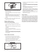
Install Pump on Tank
• Clean the tank interior of all dirt and foreign material.
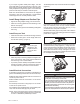
• Extend the suction pipe to its full length and insert
into the tank opening. (Figure 1)
FIGURE 1
The suction pipe
will adjust to the
length needed to
rest on the tank
bottom.
• Place the pump on the bung adapter and tighten the
union ring securely with a pipe wrench. Make sure
the union ring is not cross-threaded.
• To prevent pressure buildup and possible fuel leaks
through the nozzle, make sure the tank is vented. A
vent cap rated at 3 psi or less is recommended.
Install Electrical Connections
A grounding connection is provided. It is identied as a
green colored binding head screw in the electrical cavity.
Models M-150S and M-180S should be connected to a
12-volt DC power source.
Model M-240S should be connected to a 24-volt DC
power source.
Do not attempt connection of any pump to a 115-volt AC
or 230-volt AC power source.
For installation in unclassied areas, the supplied power
cord, fuse and strain relief grip may be used.
NOTE: These components have not been evaluated as
part of the UL Listed Equipment and are not intended
for use in a Hazardous (Classied) Location.
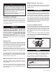
To install the power cord, remove the electrical coverplate.
(Figure 2)
FIGURE 2
If necessary, trim the power cord to the desired length.
Strip 3 to 4 inches (7.5 to 10 cm) of outer insulation
from the power cord end. Then strip 1/2 inch (1.3 cm)
of insulation from the power cord wires.
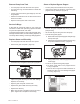
Slide the strain relief grip onto the power cord so that the
threaded end of the strain relief grip faces the stripped
power wires. (Figure 3)
FIGURE 3
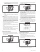
Insert the power cord through the 1/2 inch NPT connection
on the back of the pump. (Figure 4) Using wire nuts,
connect the black wire to the black wire and the red wire
to the red in the pump’s electrical cavity. Position the
wires inside the electrical cavity and tighten the strain
relief grip securely. Make sure surfaces are clean. Install
the coverplate and tighten securely.
FIGURE 4
Carefully route the power cord to the battery, protecting the power
cord from hot surfaces, sharp edges or anything that could dam-
age the power cord, resulting in a short circuit.
A fuse is provided to protect the power cord and motor. Install
fuse in the red wire of the power cord as close as possible to
the battery. Connect the red wire of the fuse to the positive (un-
grounded) side of battery. Connect black wire to the negative
(grounded) side of the battery.
Failure to follow these instructions could result in death, serious
injury or loss of equipment due to short circuit, re or explosion.
WARNING