
Product Manual


6 Rev. D 921422-18
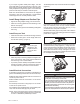
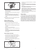
c. From inside the housing, use a small screwdriver
to push the poppet and spring through the top
outlet port. (Figure 11)
FIGURE 11
d. Wipe the poppet and gear cavities with a clean
cloth.
e. Replace the poppet, O-ring, and spring, as
necessary.
NOTE: Replace O-ring if damaged, swollen, or loose-
tting.
• To assemble, place the spring and poppet into the
poppet cavity through the top outlet port. Compress
the poppet into the housing until the poppet appears
in the lower chamber. (see Figure 10) Coat the O-ring
lightly with grease and slip over the poppet head.
Make sure the O-ring is well-seated.
• Push on the poppet through the top outlet port to
make sure it moves freely.
• Install the pipe plug again, using sealant as neces-
sary.
• Replace the gears and drive key. Make sure gears
turn freely with the key removed.
• Make sure the gear coverplate O-ring is in place.
Tighten the coverplate to the pump housing.
Replace Power Switch
• Turn the pump OFF and disconnect from power.
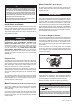
• Remove the switch coverplate from the pump hous-
ing. (Figure 12)
FIGURE 12
• Remove the torx head screw, then remove the switch
assembly. (Figure 13)
FIGURE 13
• Models M-150S and M-180S: Remove one pump
wire from the back of the switch and one wire from
the circuit protector.
• Model M-240S only: Remove both pump wires from
the back of the switch.
• Install a new switch by reversing the above procedure.
Insert the switch assembly into the pump cavity. Place
the red wire between the circuit breaker and the wall
of the pump. Make sure the O-ring is seated properly
before tightening the switch coverplate.
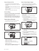
NOTE: For the proper operation of the switch lever and
cam, attach the mounting plate to the switch with a
clearance of 0.175 or about 3/16 inch. (Figure 14)
FIGURE 14
Replace Motor Protector
NOTE: The pump can remain on the tank during motor
protector replacement.
• Turn off the pump and disconnect from power.
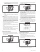
• Remove the switch coverplate from the pump hous-
ing. (Figure 15)
FIGURE 15
• Remove switch bracket mounting screw and gently
pull switch from switch cavity. (Figure 16)