
Product Manual


Before installation, wrap all threaded fuel connections
with three to four turns of thread tape or a pipe thread
sealant approved for use with petroleum fuels.
Important Information
To ensure safe operation, all fuel transfer systems must
be properly grounded.
Proper grounding means a continuous metal-to-metal
contact from one component to the next, including tank,
bung, pump, meter, lter, hose, and nozzle.
Care should be taken to ensure proper grounding
during initial installation and after any service or repair
procedures.
All factory-supplied accessories and components assure
proper grounding.
Priming
This pump is designed to self-prime with dry gears. Expect
suction lift as follows:
Manual Nozzle: 5.5 feet (1.7 m) with diesel
6.7 feet (2.1 m) with gasoline
Automatic Nozzle: 4.8 feet (1.5 m) with diesel
5.8 feet (1.8 m) with gasoline
If your installation requires a greater distance from the
lowest fuel level to the pump, the pump may not prime
until the gears are coated with uid.
To coat the gears, remove the plug on the top of the
pump (as detailed in Figure 6) and pour a small quantity
of motor oil into the gear cavity. Replace the plug, turn
the pump on, and open the nozzle.
A UL Listed foot valve with pressure relief will be required
to maintain prime.
Install Bung Adapter and Suction Pipe
Before installation, wrap all threaded fuel connections
with three to four turns of thread tape or a pipe thread
sealant approved for use with petroleum fuels.
1. Tighten the bung adapter snugly on the fuel tank.
2. Place the union ring gasket into the inlet tting on
the bottom of the pump.
3. Thread the suction pipe into the inlet tting and tighten
until snug.
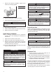
Install Pump on Tank
1. Clean the tank interior of all dirt and foreign material.
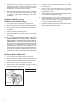
2. Extend the suction pipe to its full length and insert
into the tank opening. (Figure 1)
The suction pipe will adjust to the length needed to
rest on the tank bottom.
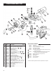
NOTE: The suction pipe supplied has a variable length
of 22 to 40 inches (56 to 102 cm). If additional length
is needed, use the 15 inch (38 cm) Suction Pipe
Extension. See the Illustrated Parts List for information
on accessories.
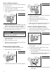
3. Place the pump on the bung adapter and tighten the
union ring securely with a pipe wrench. Make sure
the union ring is not cross-threaded.
NOTE: To prevent pressure buildup and possible fuel leaks
through the nozzle, make sure the tank is vented.
A vent cap rated at 3 psi or less is recommended.
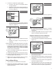
Install Electrical Connections
This pump is designed for use with 120-volt power. Do
not attempt installation on 12-volt, 24-volt or 230-volt
power sources.
It is important to exercise more than ordinary care with
electrical installation and maintenance. Failure to follow
these electrical connection instructions could result in
death or serious injury from shock, re or explosion.
Electrical wiring and connections must be made only by
a licensed electrician in accordance with national, state,
and local electrical codes regarding Class I, Division 1
requirements as well as NFPA Code 70 and 30. Other
codes may apply.
Install UL Listed, rigid metal conduit and code-specied
gasoline and oil-resistant wire with ground wire from the
switch box to the pump electrical box and use proper
seal offs.
3
Figure 1
To avoid personal injury, these instructions must
be followed.
WARNING
To avoid personal injury, make sure power is discon-
nected before removing coverplates.
WARNING
INSTALLATION