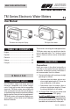
5252 East 36th Street North Wichita, KS USA 67220-3205 316-686-7361 | FAX: 316-686-6746 888-996-3837 | www.GPImeters.net SAVE THESE INSTRUCTIONS TM Series Electronic Water Meters User Manual TM Meter with Computer Display TM Digital Pulse Meter TABLE OF CONTENTS These meters are not legal for trade applications. English............................................................1 Español...........................................................8 Deutsch...............................................
3. Attach meter with arrow pointed in the direction of fluid flow. 4. For NPT and BSP Fittings - Hand tighten the meter at the housing ends. Do not use a wrench or similar tool to tighten. This can damage the housing. WARNING Compatibility of this product’s material and the process fluid and/or environment should be considered prior to putting into service. WARNING Product should never be operated outside its published specifications for temperature or pressure. See specifications for your model.
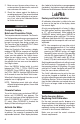
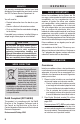
Wiring Diagram 2 SQUARE WAVE OUTPUT White 6 volt Square Wave Signal Terminal Block 1 Customer Interfacing Equipment 2 3 4 Black Common (Ground) The terminal block is identified as follows: Pin #1 6 volt square wave Pin #2 +9 to 35 volt DC Input (not used) Pin #3 Common Ground Pin #4 Open Collector signal Output (not used) Conditioned Signal Output Module Wiring This conditioned signal output module can be wired to provide an open collector signal output or 6-volt square wave output.
2. Meter an exact known volume into an accurate container. For best results, meter with one continuous full stream. 3. Check the volume against the display or recording equipment. If the amount metered is accurate, further calibration is not necessary. If not, refer to the Calibration Section for further instructions. OPERATION Computer Display – Batch and Cumulative Totals The computer maintains two totals. The Cumulative Total provides continuous measurement and cannot be manually reset.
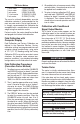
TM Series Meters ½ inch meter ¾ inch meter 1 inch meter 1 ½ inch meter 2 inch meter 1 GPM (3.8 LPM) 2 GPM (7.5 LPM) 5 GPM (18.8 LPM) 10 GPM (37.5 LPM) 20 GPM (75 LPM) The use of a uniformly dependable, accurate calibration container is recommended for the most accurate results. Due to high flowrate, it is strongly recommended that calibration be completed with a combination of volume and weight using fine resolution scales.
Battery Replacement The computer display is powered by two 3-volt lithium batteries which may be replaced while the meter is installed. When batteries are removed or lose power, the batch and cumulative totals and the field and factory calibrations are retained. WARNING (Battery) – Avoid mechanical or electrical abuse. Batteries may explode or cause burns, if disassembled, crushed or exposed to fire or temperatures in excess of 212°F (100°C). Do not short circuit or install with incorrect polarity.
U.S. Measurement Operating Temperature: 0° to +60° C (Do not allow fluid to freeze inside meter.) Unit of Measure: Gallon Flow Range: ½ inch ¾ inch 1 inch 1 ½ inch 2 inch Storage Temperature: –40° to +70° C 1 - 10 GPM 2 - 20 GPM 5 - 50 GPM 10 - 100 GPM 20 - 200 GPM Accuracy with Computer: ± 3.0% of reading (Accuracy can be improved with field calibration) Operating Temperature: +32° to +140° F (Do not allow fluid to freeze inside meter.) Product Weight:* Spigot (Pipe) ½ inch .172 kg ¾ inch .
SERVICE For warranty consideration, contact your local distributor. If you need further assistance, contact the GPI Customer Service Department at: 1-888-996-3837 You will need to: • Provide information from the decal on your meter. • Receive a Return Authorization number. • Flush any fluid from the meter before shipping to the factory. If possible leave customer installed fittings or ample length of bare pipe for reinstallation.
3. Coloque el medidor con la flecha orientada en sentido del caudal del líquido. Señal de Salida Condicionada Cableado de Módulo 4. Para conexiones NPT y BSP - Ajuste manualmente el medidor en los extremos del alojamiento. No utilice una llave ni una herramienta similar para el ajuste. De esa manera puede dañar el alojamiento. Este módulo de Señal de salida condicionada se puede conectar para proporcionar una salida de colector abierta o de señal de onda cuadra de 6-voltios.
Verificar la Exactitud del Metro Antes de usar, comprobar la exactitud del metro y verificar la calibración. 1. Cerciorarse de que no haya aire en el sistema comenzando el flujo hasta que funciona constantemente. Entonces, detener o desviar el flujo mediante una válvula o la boquilla. 2. Con el medidor, mida un volumen exacto en un envase exacto. Para mejores resultados, medir con una corriente complete y continua. 3. Comprobar el volumen con lo indicado en la pantalla o el equipo de grabación.
Los “campos” de calibración pueden ser configurados por el usuario, y puede ser cambiado o modificado en cualquier momento mediante el procedimiento de calibración se describe a continuación en la sección de calibración. De los totales o caudal de agua derivada de la calibración de campo se invoca cuando el icono de la FAC ya no es visible en la línea superior de la pantalla.
calibración en algunas situaciones. Por ejemplo, las condiciones extremas de temperatura, las configuraciones de plomería estándar o con otros líquidos distintos del agua. MANTENIMIENTO La utilización y el cuidado apropiados amplia-rán la vida y el servicio del medidor. Rotor de Turbina El medidor practicamente no tiene necesidad de mantenimiento. Sin embargo, es importante que los movimientos del rotor ocurran libremente. Mantener el medidor limpio y libre de contaminantes.
humedad, cerciorarse de que el anillo esté asentado completamente. Apretar los cuatro tornillos en la placa frontal.
Peso del Producto - kgs:* Espita (Enchufo Macho) ½ pulgada ,172 ¾ pulgada ,195 1 pulgada ,222 1 ½ pulgada ,299 2 pulgada ,354 NPT ,249 ,304 ,381 ,626 ,807 BSP N/A N/A ,381 ,666 ,875 Dimensiones - Centímetro (L x H x W): ** Sin Conexión ½" ¾" 1" 1 ½" 2" ½” ¾” 1” 1 ½” 2” * ** 5,0 x 6,6 x 9,6 5,0 x 6,8 x 9,6 5,0 x 7,8 x 10,4 5,8 x 9,3 x 13,7 6,0 x 10,6 x 13,9 Con conexión NPT 5,0 x 7,1 x 13,9 5,0 x 7,3 x 13,9 5,0 x 8,3 x 15,7 5,8 x 9.
PRECAUCIÓN No devolver el metro sin la autoridad específica del departamento de servicios al cliente de GPI. Debido a las regulaciones terminantes gubernamentales GPI no aceptará los medidores para la reanudación a menos que estén totalmente libres de residuos líquidos peligrosos o inflamables, o líquidos de todos tipos durante el transporte, la dirección, y la disposición.
Sicherstellen, dass das Klebeband nicht den Durchflussweg stört. 3. Das Messgerät mit dem Pfeil in Richtung der Flüssigkeitsströmung befestigen. 4. Bei NPT- und BSP-Verschraubungen: Das Messgerät an den Gehäuseenden handfest anziehen. Keinen Schraubenschlüssel oder ein ähnliches Werkzeug zum Anziehen verwenden. Dies kann das Gehäuse beschädigen. WARNUNG Die Kompatibilität des Werkstoffs dieses Produkts und des Prozessmediums und/ oder der Umgebung müssen vor der Inbetriebsetzung berücksichtigt werden.
10 Fuß (3 m) Kabel wird mit dem Modul versehen. Das Kabel zur gewünschten Länge trimmen oder das Kabel wie benötigt verlängern. MeßinstrumentGenauigkeit Überprüfen Bevor Sie verwenden, die Genauigkeit des Meßinstruments überprüfen und die Kalibrierung überprüfen. 1. Überprüfen, daß es keine Luft in der Anlage gibt, indem Sie den Fluß beginnen, bis er ständig läuft. Dann, zu stoppen oder umzuleiten den Fluss mit einem Ventil oder eine Düse. 2.
Wechseln zwischen verschiedenen Einheiten werden nicht beschädigt die Total-Inhalten. Zum Beispiel, im GL-Modus, den Computer summiert 10,00 Gallone, wenn der Benutzer schaltet in den LT, erscheint auf dem Anzeige 37,85 Liter (das gleiche Volumen, verschiedene Einheit) zu lesen. Das “Feld” Kalibrierung kann vom Anwender eingestellt werden und kann geändert werden, oder jederzeit über das Kalibrierverfahren um nachstehend beschriebenen Abschnitt der Kalibrierung. Summen bzw.
festgestellt. Dieser K-Faktor kann für Kalibrierung “des einzelnen Punktes” verwendet werden und wird eine annehmbare Genauigkeit liefern. Jedoch können die Messwerte möglicherweise nicht genau sein, wenn Sie diese Kalibrierung Methode in einigen Situationen verwenden. Zum Beispiel, extreme Temperaturen, NichtStandard-Sanitär-Konfigurationen oder mit anderen Medien als Wasser. WARTUNG Die korrekte Behandlung und die Wartung verlängern das Leben und den Service des Meßinstruments.
3. Neue Batterien anbringen. Überprüfen, daß der positive Pfosten in der richtigen Position ist. 4. Wenn die Batterien ausgetauscht sind,zeigt die Frontplatte “POWER ON”. Die Anzeige überprüfen, um normale Funktionen sicherzustellen, bevor Sie wieder zusammenbauen. 5. Falls nötig, Batterieeinsetzung berichtigen, und die Frontplatte auf das Turbinegehäuse in Position bringen. Um Feuchtigkeitsbeschädigung zu vermeiden, überprüfen, daß der dichtung völlig sitzt.
Genauigkeit mit Computer: ±3.0% des Lesens (Genauig-keit kann mit verbessert werden auffangen Kalibrierung) Betriebstemperatur: 0° zu +60° C (Flüssigkeit nicht innerhalf des Meßinstruments einfrieren lassen.) SpeicherTemperatur: -40° zu +70° C Gewicht des Produktes - kgs.
VORSICHT Das Meßinstrument nicht ohne die spezifische Berechtigung der GPI-Kundendienstabteilung zurückbringen. Wegen der strengen Regelungen des Transportes, der Behandlung und der Beseitigung der gefährlichen oder feuergefährlichen Flüssigkeiten, nimmt GPI nicht Meßinstrumente für Überarbeitung an, es sei denn, class sie vom flüssigen Überrest vollständig frei sind. WEEE RICHTLINIE Der Richtlinie 2002/96/EG über Elektro- und Elektronik-Altgeräte (WEEE) des Europäischen Parlaments bzw.
4. Per i raccordi NPT e BSP - Serrare manualmente lo strumento alle estremità degli alloggiamenti. Non usare chiavi o attrezzi simili per il serraggio. Potrebbero danneggiare l’alloggiamento. ATTENZIONE Prima della messa in servizio occorre valutare la compatibilità del materiale di questo prodotto e il fluido di processo e/o l’ambiente. ATTENZIONE Non usare mai il prodotto fuori dai limiti di temperatura o pressione specificati. Fare riferimento alle specifiche del modello interessato.
Verificare L’Esattezza del Tester Caratteristica Indice di Flusso 1. Assicurarsi che non ci è aria nel sistema iniziando la quantità di fluido fino a che non funzioni costantemente. Poi, fermare o deviare il flusso con una valvola o ugelli. Per utilizzare questa funzione, premere e rilasciare DISPLAY fino FLOWRATE appare l’icona. La fabbrica di base di tempo sarà evidenziato al diritto della FLOWRATE (M = minuti, H = ore, D = giorno).
Il “campo” di taratura può essere impostato dall’utente, e può essere cambiato o modificato in qualsiasi momento, utilizzando la procedura di taratura descritta di seguito nella sezione di calibrazione. Totali o portata derivata dalla taratura campo vengono richiamati quando l’icona FAC non è più visibile sulla riga superiore del display.
MANUTENZIONE Il maneggiamento e la cura adeguati estenderanno la durata ed il servizio del tester. Rotore di Turbina Il tester è virtualmente manutenzione-free. Tuttavia, è liberamente importante i movimenti del rotore. Mantenere il tester pulito ed esente dagli agenti inquinanti. Se il rotore non gira liberamente, applicare un lubrificante penetrante sul rotore, sull’albero e sui cuscinetti. Rimuovere tutti i residui o depositi dal rotore usando una spazzola molle o una piccola sonda.
SPECIFICHE Ingresso e Presa: Montaggi Spigot (Tuboture) Scade TM050/TM050-P ½" Programma 80, Spigot (Tuboture) TM075/TM075-P ¾" Programma 80, Spigot (Tuboture) TM100/TM100-P 1" Programma 80, Spigot (Tuboture) TM150/TM150-P 1 ½" Programma 80, Spigot (Tuboture) TM200/TM150-P 2" Programma 80, Spigot (Tuboture) Montaggi del NPT TM050-N/TM050-N-P ½ pollice NPT TM075-N/TM075-N-P ¾ pollice NPT TM100-N/TM100-N-P 1 pollice NPT TM150-N/TM150-N-P 1 ½ pollice NPT TM200-N/TM200-N-P 2 p
2 pollice ,354 ,807 ,875 Dimensioni - Centimetro (L x H x W):** Senza Montaggio Con raccordo NPT ½" ¾" 1" 1 ½" 2" ½” ¾” 1” 1 ½” 2” 5,0 x 6,6 x 9,6 5,0 x 6,8 x 9,6 5,0 x 7,8 x 10,4 5,8 x 9,3 x 13,7 6,0 x 10,6 x 13,9 5,0 x 7,1 x 13,9 5,0 x 7,3 x 13,9 5,0 x 8,3 x 15,7 5,8 x 9,9 x 19,3 8,8 x 11,4 x 20,0 Con raccordo BSP N/A N/A 5.3 x 7.9 x 17.0 5.6 x 9.4 x 19.3 6.9 x 10.7 x 19.8 ** Il peso con il visualizzatore del computer. Il modulo di segnale condizionato produrre aggiungil ,14 kg.
WIII DIRETTIVA La direttiva 2002/96/EC del Parlamento europeo e del Consiglio dell'Unione europea sui rifiuti di apparecchiature elettriche ed elettroniche (RAEE) e stato aprovatto del Parlamento europeo e del Consiglio dell'Unione europea.
3. Fixer le compteur avec la flèche dirigée dans le sens du débit de liquide. Le Signal de Sortie Conditionné le Câblage de Module 4. Pour les raccords NPT et BSP - Serrer le compteur à la main au niveau des extrémités du boîtier. Ne pas utiliser de clé ou d’outil similaire pour serrer. Cela risque d’endommager le boîtier. Ce module du signal de sortie conditionné peut être installer pour fournir un signal ouvert collecteur de sortie ou un signal carré de sortie de 6-V.
Vérifiez l’Exactitude de Compteurs La Caractéristique du Débit Avant l’utilisation, vérifiez l’exactitude du compteur et vérifiez le calibrage. Pour utiliser cette fonction, appuyez sur la touche DISPLAY de libération avant que l’icône FLOWRATE apparaît. L’usine de définir la base de temps sera mis en évidence à la droite du débit (M = minutes, H = heures, d = jours). Cuand FLOWRATE est invoquée, l’affichage sera en indiquant le taux d’écoulement. 1.
Le champ étalonnage mai fixé par l’utilisateur, et peuvent être changés ou modifiés à tout moment en utilisant la procédure d’étalonnage décrite cidessous dans la section de calibrage. Certains totaux ou de débit provenant de l’étalonnage sur le terrain sont invoquées lorsque l’icône FAC n’est plus visible sur la ligne supérieure de l’écran. CALIBRAGE Avant de Commencer le Calibrage de Champ Pour les résultats les plus précis, distribuez au débit qui simule mieux vos conditions de fonctionnement réelles.
non standard ou de plomberie avec d’autres fluides que l’eau. ENTRETIEN La manipulation et le soin appropriés prolongeront la vie et le service du compteur. Rotor de Turbine Le compteur est pratiquement exempt d’entretien.Cependant, il est important que les rotor bouge librement. Maintenez le compteur propre et exempt des contaminations. Si le rotor ne tourne pas librement, appliquez un lubrifiant pénétrant sur le rotor, l’axe et les roulements.
CARACTÉRISTIQUES Admission et Sortie: Spigot (Pipeau) Fin de Modèle TM050/TM050-N Programme 80, Spigot (Pipeau) de ½" TM075/TM075-N Programme 80, Spigot (Pipeau) de ¾" TM100/TM100-N Programme 80, Spigot (Pipeau) de 1" TM150/TM150-N Programme 80, Spigot (Pipeau) de 1 ½" TM200/TM200-N Programme 80, Spigot (Pipeau) de 2" Raccordements de NPT de Modèle TM050-N/TM050-N-P NPT de ½" TM075-N/TM075-N-P NPT de ¾" TM100-N/TM100-N-P NPT de 1" TM150-N/TM150-N-P NPT de 1 ½" TM200-N/TM200-N-P NPT de 2" Modèles B
Les Poids de Produit - kgs.: * Spigot (Pipeau) NPT ½ inch ,172 ,249 ¾ inch ,195 ,304 1 inch ,222 ,381 1 ½ inch ,299 ,626 2 inch ,354 ,807 125516-03 125516-04 BSP N/A N/A ,381 ,666 ,875 Les Dimensions - cm (W x H x L):** ½" ¾" 1" 1 ½" 2" ½” ¾” 1” 1 ½” 2” Sans Raccord Avec raccord NPT 5,0 x 6,6 x 9,6 5,0 x 7,1 x 13,9 5,0 x 6,8 x 9,6 5,0 x 7,3 x 13,9 5,0 x 7,8 x 10,4 5,0 x 8,3 x 15,7 5,8 x 9,3 x 13,75,8 x 9,9 x 19,3 6,0 x 10,6 x 13,9 8,8 x 11,4 x 20,0 Avec raccord BSP N/A N/A 5.3 x 7.
WEEE DIRECTIVE Le Waste Electrical and Electronic Equipment (WEEE) directive (2002/96/EC) a été approuvé par le Parlement Européan et le Conseil de l’Union Européene en 2003. Ce symbole indique que ce produit contient l’équipement électrique et électronique qui peut inclure les batteries, les cartes électroniques les affichages à cristaux liquides ou d’autres composants qui peuvent être sujets à des règlements locaux de disposition à votre endroit.
Declaration of Conformity Manufacturer's Name: Manufacturer's Address: Great Plains Industries, Inc. 5252 East 36th Street North Wichita, KS USA 67220-3205 Declares, that the product: Product Name: Conditioned Signal Module TM Series Water Meter/Pulse Out Model Numbers: 0N-0278 TM***-B-P TM***-P TM***-D-P TM***-N-P TM***-F-P Model numbers include all combinations of an alpha-numeric series as illustrated above.
Declaration of Conformity Manufacturer's Name: Manufacturer's Address: Great Plains Industries, Inc. 5252 East 36th Street North Wichita, KS USA 67220-3205 Declares, that the product: Product Name: TM Series Water Meter Model Numbers: TM050 TM200 TM075 TM300 TM100 TM400 TM150 Model numbers may include the suffix "-N", "-B", "-F" or "-D" to indicate thread or flange type.
Limited Warranty Policy Great Plains Industries, Inc. 5252 E. 36th Street North, Wichita, KS USA 67220-3205, hereby provides a limited warranty against defects in material and workmanship on all products manufactured by Great Plains Industries, Inc. This product includes a 1 year warranty.