Digital and Analog Versions Owner’s Manual Revision D ACU Firmware v1.13 RCU Firmware v1.13 XMOS Firmware v1.
1 Welcome Welcome and thanks for purchasing the Grace Design m905 reference monitor controller. We build all of our products to be completely reliable and straightforward to use, so you can concentrate on doing great work. While you will find the m905 is fairly straightforward to use, it is a very powerful unit and a great deal of user configuration is possible, so we recommend that you spend some time reading this manual to help avoid any common user difficulties.
2 Important Safety Information • Indoor use only • Ordinary Protection: This equipment should not be exposed to dripping or splashing • Avoid placing objects filled with liquids, such as vases or glasses, on this equipment • Class I Equipment (grounded type) • Electrical rating: 100-240V~ 50-60Hz 60W • Mains supply voltage fluctuations are not to exceed ±10% of the nominal supply voltage • Pollution Degree 2 • Installation (Overvoltage) Category II for transient overvoltages • Maximum Relative Humidity: <80
5 m905 features • Analog inputs - unbalanced, balanced (2nd pair balanced available on m905 Analog) , CUE, talkback mic • Digital inputs - 2x AES3, 1 S/PDIF, 1 TOSLINK, ADAT (selectable in 4 pairs, or 2 pairs in S/MUX), USB, AES3 Dual Wire mode. AES and S/PDIF connectors support DSD64 or DSD128 via DoP Version 1.1 • Audio circuitry designed for completely transparent and musical playback performance • Asynchronous Class 2 USB playback supports up to 24bit /196kHz and DSD64 or DSD128 via DoP Version 1.
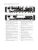
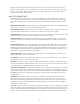
M905 AUDIO CONTROL UNIT REAR PANEL 2 3 4 1 6 7 8 5 10 9 DIGITAL OUT DIGITAL IN OUT 11 SUB/ DAC OUT L 12 CUE OUT L R 13 R TALKBACK OUT 1M 100-240 VAC / 50-60Hz 60 Watts Max 75 IN WORDCLOCK AES 1 AES 2 S/PDIF TOSLINK ADAT USB 2 AES3 S/PDIF L Pb RoHS COMPLIANT R GRACE DESIGN LYONS, CO USA L UPGRADE 14 REMOTE TALKBACK SWITCH 15 R L SPEAKER 1 16 R L SPEAKER 2 17 R L SPEAKER 3 18 L R CUE IN 19 R BALANCED IN 20 UNBAL IN 22 21 TALKBACK MIC IN 23 24 SUB
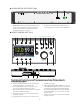
AUDIO CONTROL UNIT FRONT PANEL 1 2 REFERENCE MONITOR CONTROLLER GRACE DESIGN USA 1 2 HEADPHONE OUTPUT standard TRS 1/4” jack for headphones. Wired in parallel with the jack on the RCU. Connection to headphones should be made using standard ¼” TRS stereo connectors. AC mains power standby switch Illuminates green when m905 system is powered on.
8 9 10 11 12 13 14 15 16 AES selects the last used AES source. Once selected, pushing the switch toggles between AES1 and AES2. USB selects computer input source connected to the USB connector. Speakers 1, 2, 3 illuminated switches select any one pair of the three available speaker outputs. Mute / solo switch mutes the speakers or press and hold to toggle solo channel. Dim / x-feed reduces the monitoring level by a prescribed amount. Press and hold to toggle on / off cross-feed in headphones.
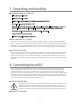
7 Unpacking and Installing YOUR m905 BOX WILL CONTAIN • The Audio Control Unit (ACU) • The Remote Control Unit (RCU) • The RCU tilt base and accompanying hardware, premounted to the RCU • 25’ serial cable to connect the RCU and ACU • m905 Analog comes with an ethernet cable and 2 serial adapter jacks . For RCU headphone operation a RCU cable ugrade is required.
Before powering up your m905, make sure your monitor speakers or power amps connected to your monitors are turned OFF. Once the m905 and the rest of your audio system are powered up, turn on the power to your speakers. When powering down, we recommend that you first power off your speaker system and then power down the m905. SYSTEM CONNECTIONS The m905 input, output and interface connections are detailed here.
anced equipment. (p.37) SUB / DAC / METER OUTPUT - Meter OUTPUT – Can be configured as either two mono balanced subwoofer outputs, one stereo subwoofer output, a stereo balanced fixed DAC output, or a stereo balanced configurable meter output.. These output options are configurable in the setup menu. Subwoofer outputs settings are configured with each speaker output. As a DAC out, the last selected digital input is converted and sent to this output at all times.
talkback function can be activated at both the RCU and the remote switch. See the remote talkback cable diagram at the end of this manual for connection details. 9 Normal Operation Mode m905 operation is categorized in two different modes: normal operation mode and setup mode. Once the RCU and ACU are connected and power is turned on, the system boots up into normal operation mode.
The m905 utilizes a single rotary pushbutton encoder for control of the speaker and headphone volume levels, level preset recall and headphone mute. Switching between speaker level and headphone level control is done by pushing and releasing the volume control knob. The current volume levels are indicated on the display with the active control being green and the inactive control in light gray.
SOLO mode provides a means to monitor left or right channel program material exclusively. When SOLO mode is active, the button flashes red. The active SOLO channel is indicated on the speaker and headphone status display. In left channel SOLO mode, the right channel is muted in the speaker and headphone outputs.* In right channel SOLO mode, the left channel is muted in the speaker and headphone outputs.* (NOTE: Enabling MONO during SOLO mode routes the active solo channel to both left and right outputs.
PRESS AND HOLD BUTTON: • Toggles the headphone x-feed mode on and off. MONO / (L-R) - The multi-function MONO / (L-R) button controls the MONO and the LEFT minus RIGHT features. MONO sums the left and right channels and provides this signal to both the left and right channels of the speaker and sub outputs (if stereo sub is configured). The headphone output also becomes MONO if the headphone mono control is enabled (configured in SETUP).
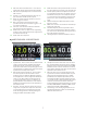
THE DAC STATUS PROVIDES THE FOLLOWING INFORMATION: • Selected digital input source / demphasis (if enabled) / s/mux (if enabled) • Sample rate (PCM or DSD) / s-lock status (if active) • Selected clocksource / selected clocksource lock status. If the system is unable to lock to the selected clocksource (other than the recovered clock), the dac will be clocked of the recovered clock and selected clocksource will flash red.
APPLE IR REMOTE CONTROL OPERATION - In addition to the Grace Design wireless remote control, the m905 can also be controlled by an Apple IR Remote Control. The following section details all of the features available from the Apple IR Remote Control. Several of the buttons on the remote have dual functions, accessed by either a ‘press and release’ or a ‘press and hold’ action, and are described below.
ANALOG ONLY OPTION The m905 is now available without the built in Digital to Analog converter section. The Analog version may updated to the Digital version at any time. • Inputs are shown across the bottom and are (in this order) balanced, balanced 2, unbalanced and cue • Inputs across the top are dark gray and pressing the associated input button has no response.
The system remembers the last selected parameter in each setup mode and returns to that setting when each setup mode is entered. In the following sections, each of the controls and features of the setup mode will be detailed. All system setup parameters are stored in non-volatile memory. At any point the setup mode can be exited with the following actions: TO EXIT AND SAVE CHANGES: • Press and release the setup button to save all setup parameters, exit setup mode and return to normal operation.
CLOCKSOURCE - The clocksource can be independently selected for each digital input. Available options are current input and wordclock. When the clock source matches the input name, the DAC is clocked off the recovered digital audio clock. When wordclock is selected, the DAC is clocked off the wordclock input. The USB input provides the clocksource options of internal, wordclock, ADAT and TOS/S/PDIF/AES.
SPEAKER SETUP Pressing any of the speaker buttons selects that output for the monitoring path (exactly as it does in normal mode) and brings up the setup information for that speaker output. The following are the details of each of the speaker setup parameters. SPEAKER NAME - This parameter allows the user to customize the displayed name for each speaker output. For this parameter, the control is a little different, but again, you will remember how to do this from getting the high score on Asteroids.
default is 0.0. DISPLAY MODE (GLOBAL) - This parameter sets the speaker output display mode. When standard level is selected, the speaker level is displayed as a 0-100 range in 0.5dB steps. When reference level is selected, the speaker level is displayed as a 100dB range in 0.5dB steps based on the ref. level setting (see below). This parameter is the same for all speaker outputs.
The SUB/DAC/METER setup parameters are as follows: OUTPUT MODE - This parameter configures the SUB/DAC/METER output function. Available options are sub output, DAC output and meter output. The default is sub output. Note: DAC output mode and settings not available on m905 Analog units. When sub output is selected, this output acts as the dedicated subwoofer output and is configured based on the speaker sub output settings in the speaker setup.
“center”. The default is center. DIM ON TALKBACK - Both the internal m905 RCU talkback mic signal or the external talkback mic signal can be summed with the cue output. When the talkback is active, the source material can be attenuated to make the talkback easier to hear. The available dim on talkback range is -35dB to 0dB in 0.5dB steps. The default is -20dB. HEADPHONE SETUP From the setup screen, press and hold the knob to enter headphone setup mode.
TALKBACK SETUP From the setup screen, pressing the talkback button enters talkback setup mode. Once talkback setup mode is active, pressing the talkback button will have the same function as it does in normal mode. The m905 features a flexible talkback system for communicating with the performers. Two different talkback sources are available - 1) Built-in mic on the RCU and 2) external mic input on the ACU. Each of these have independent controls and setup.
There are no setup parameters associated with the mute / (solo) control. In setup mode, the mute / (solo) button functions exactly as it does in normal operation mode. 11 General Setup Other general setup options and information are accessed from the setup screen by pressing the MONO button.
REMOTE ID - this is a read-only parameter that displays the id number of the paired Apple IR remote (if remote pairing = yes). This can be usful when trying to identify multiple remotes in your environment. L/R CONTROLS - This parameter selects the function for the left / right arrows on the Apple remote. Available options are: • input – in this mode the left and right buttons on the Apple remote scroll through each input.
*In addition to the ADAT / AES DUALWIRE configuration in SETUP, hardware jumper J7 on the AT166 pcb must be placed in the correct position for proper operation. The default position selects the ADAT input. These jumpers are shown in the ‘m905 DIGITAL I/O PCB Jumper Locations’ diagram, page 40. To set the ADAT/AES Dual Wire mode: • Disconnect the m905 from its AC power by unplugging the AC power cable. • Use a #2 Phillips screwdriver to remove the top cover from the m905.
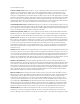
RESPONSE - The response controls the ballistics of the SPL meter. Available options are slow and fast. The default is fast. 12 ABOUT CROSS-FEED When listening to loudspeakers in a room, your left ear hears sound primarily from the left speaker (and vice versa) but also receives a signal from the right speaker at a lower level and with some time delay compared to the right ear.
+5 +0 -5 Direct Signal -10 -15 -20 dB Crossfeed signal -25 -30 -35 -40 -45 -50 -55 20 50 100 200 500 1k 2k 5k 10k 20k 50k Hz 13 Communication Error Handling If at any point communication is lost between the RCU and ACU, the remote will display the communication error message and begin attempting to re-establish communication. During this time, the ACU remains in the last configured state.
USB UP CHANNEL SETUP In addition to playback, the m905’s USB interface allows for up to 10 channels to be transmitted back to the computer. These ‘up channels’ allow the user to use the m905 as a simple I/O computer interface. Up channel operation is configured in the PC’s USB Audio Driver Control Panel or Apple OSX Audio MIDI Setup. Two modes are available. The first option configures the device for 10 input channels and 2 output playback channels.
For PC, the input stream format is selected in the USB Audio Driver Control panel as shown: Note: If your application does not require more than 2 input channels, the 2 input/2output setting is recommended as it requires less over all bandwidth of the USB connection. COMPUTER AUDIO REQUIREMENTS Regardless of the type of computer you will use to playback audio from, it must have at least one available USB port. The m905 ships with a standard USB type A to type B cable.
Different operating systems may pose their own set of complications in setting up the m905 as the audio playback device. In the event that ‘plug and play’ operation does not occur, you will need to look at some specific setup variables for your OS. In this case, we will direct you to a very well written and comprehensive document by our friend and colleague Charlie Hanson from Ayre Acoustics. http://www.ayre.com/usb.
UPDATING RCU FIRMWARE TO UPDATE THE FIRMWARE ON THE m905 RCU PERFORM THE FOLLOWING STEPS: • Download the m905 RCU firmware package from the Grace Design website and unzip it on your computer. • Turn off the m905 and connect your computer via USB to the USB upgrader port on the m905 RCU. • Turn on the m905. The setup button will illuminate solid white on the remote control to indicate USB upgrader mode is active. Note that the LCD display will be dark.
• If the m905 RCU encounters any problems during the USB upgrade process, the folder will contain a file named “ERROR.TXT”. • The type of problem encountered is reported on the Status line in ERROR. TXT. In this example, a firmware file for the ACU was accidentally uploaded as indicated by the “Invalid Device” error. Should an error occur, restart the firmware upgrade process. • Disconnect the USB cable from the RCU and then cycle the power to the m905.
• Once the reprogramming is complete, the m905 RCU will disconnect/reconnect itself from the computer. Open the folder again. The file named “SUCCESS.TXT” should be in the folder. This is your indication that the firmware update process has completed successfully. • If the m905 ACU encounters any problems during the USB upgrade process, the folder will contain a file named “ERROR. TXT”. • The type of problem encountered is reported on the Status line in ERROR.TXT.
• Select Firmware Upgrade from the menu: • Click the Browse button and locate the m905_XMOS_DFU_xxx.bin file and select it. • Click on Start Firmware Upgrade to begin the XMOS firmware upgrade process. • The progress of the upgrade will be indicated in a pop-up dialog box. DO NOT DISCONNECT THE DEVICE OR INTERRUPT POWER TO THE m905 WHILE THIS IS IN PROCESS. Once completed, power cycle the system. Should the firmware upgrade fail, start the XMOS firmware upgrade process over again.
16 Specifications ANALOG I/O THD+N at Maximum Volume, 1kHz, 22Hz-22kHz BW +20dBu out +10dBu out 0dBu out Intermodulation Distortion SMTPE/DIN 4:1 50Hz, 7kHz @+20dBu out @ 0dBu out Frequency Response Balanced Inputs +/-3dB Unbalanced Input +/-3dB Dynamic Range 20-22kHz bandwidth 20-22kHz bandwidth and A weighting filter Output Noise 20-22kHz bandwidth, at -20dB gain 20-22kHz bandwidth and A weighting filter, at -20dB Gain Phase Deviation 20Hz to 20kHz 10Hz to 100kHz Crosstalk any channel 100Hz 1kHz 20kHz Bal
DIGITAL TO ANALOG CONVERTER FIXED OUTPUTS Output Levels User selectable (0dBFS) Fixed output trim range (0.5dB steps) THD+N 1kHz, -1dBFS, (0dBFS = +20dBu), 20-22kHz bandwidth Dynamic Range 20-22kHz bandwidth, 0dBFS = +20dBu (AES17 filter) 20-22kHz bandwidth, 0dBFS = +20dBu (A-weighted) Input Lock Range AES3/SPDIF 44.1kHz 48kHz 88.2kHz 96kHz 176.4kHz 192kHz ADAT LIGHTPIPE™ 44.1kHz 48kHz 88.2kHz 96kHz ADAT LIGHTPIPE™ 44.1kHz 48kHz 88.2kHz 96kHz s-Lock™ Capture Range 44.1kHz 48 kHz 88.2 kHz 96 kHz 176.
10 CH 2 CH 2 CH INPUT SELECTORS DIGITAL LOOP THROUGH WORDCLOCK/LOOPSYNC IN SPDIF OUT AES3 OUT ADAT SPDIF TOSLINK AES3 2 AES3 1 USB-2.
18 PCB Jumper Locations REAR PANEL m905 MAIN PCB JUMPER LOCATIONS P165 Rev B ADAT REAR PANEL AES 2 WIRE J7: AES DUAL WIRE / ADAT SELECT m905 DIGITAL I/O PCB JUMPER LOCATION P165 Rev A 40
19 Wiring Diagrams DB15 15 pin RCU connector, RS485 operation PIN 1 Connector back side veiw. Both cable ends are identical. RX- PIN 2 GND PIN 3* TX- PIN 4* +5VDC PIN 5* GPIO PIN 6 TALKBACK- PIN 7 HEADPHONE LEFT PIN 8 HEADPHONE GND PIN 9 RX+ PIN 10* TX+ PIN 11 +6.5VDC PIN 12* +3.3VDC PIN 13 TALKBACK PIN 14 GND PIN 15 HEADPHONE RIGHT * presently unconnected, provisional for RS422 operation Do not use an off the shelf DB15 cable as the pinout will be incompatable.
20 Cleaning and Maintenance Your m905 system chassis is constructed out of high quality anodized T6 aluminium. Under normal circumstances, virtually no maintenance is required to keep the unit looking shiny and new. However, if you unit becomes smudged or dirty, here are some cleaning tips: Apply windex to a clean lint free cloth and gently wipe all surfaces, taking care not to allow the cleaning product to build up around any panel switches or knobs.
22 Manual Revisions REVISION PAGE CHANGE DATE INITIALS A all initial release 1/30/2013 edg B all added DSD references 3/26/2013 edg added reference level information added dual wire AES operation C 1 changed ACU, RCU & XMOS firmware Rev to 1.