
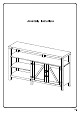
Installation & Assembly
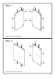


Step 8
Step 7
P.8
21 3
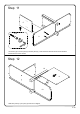
Attach parts (16) and (17) to part (4), and then attach cam locks (C) to fully assemble part (4).
Please note in the diagram that the holes for the adjustable shelf on part (3) are on the same side as the
21 3
C
C
C
C
C
C
C
C
C
C
C
C
4
3
3
16
17
14
15
18
19
Attach parts (14,15) and (18,19) to part (3), and then attach cam locks (C) to fully assembled part (3) ,
groove for the back panel on parts (14,19).