309388 Operating Instructions 150 RPX Pressure Roller and Spray System Rev. J – For roller and portable spray application of architectural paints and coatings – Model 233687, Series B 2800 psi (193 bar, 19 MPa) Maximum Working Pressure* * The best operating pressure is the lowest pressure that provides an even paint supply to the roller and typically does not exceed 300 psi (2.1 MPa, 21 bar). Also Includes: ContractortIn–line Valve 244161 and Pressure Roller 244279 D D D D 20 in.
Specifications This equipment is not intended for use with flammable or combustible materials used in places such as cabinet shops or other “factory” or fixed locations. If you intend to use this equipment in this type of application, you must comply with NFPA 33 and OSHA requirements for the use of flammable and combustible materials. The following are general warnings related to the setup, use, grounding, maintenance, and repair of this equipment.
SKIN INJECTION HAZARD High pressure fluid from gun, hose leaks, or ruptured components will pierce skin. This may look like just a cut, but it is a serious injury that can result in amputation. Get immediate surgical attention. D Do not point gun at anyone or any part of the body. D Do not put your hand over the spray tip. D Do not stop or deflect leaks with your hand, body, glove, or rag. D Engage trigger lock when not spraying.
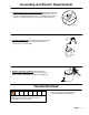
Grounding and Electric Requirements The sprayer must be grounded. Grounding reduces the risk of static and electric shock by providing and escape wire for the electrical current due to static build up or in the event of a short circuit. ti3001b D The sprayer requires a 120V AC, 60 Hz, 15A circuit with grounding receptacle. Never use an outlet that is not grounded or an adapter. D Do not use the sprayer if the electrical cord has a damaged ground prong.
Grounding and Electric Requirements D Ground solvent pails used when flushing. Follow local code. Use only conductive, metal pails, placed on a grounded surface such as concrete. Do not place the pail on a non–conductive surface such as paper or cardboard, which interrupts the grounding continuity. ti5850a D Ground the metal pail by connecting a ground wire to the pail by clamping one end to pail and the other end to ground such as as water pipe.
Pressure Relief Procedure 1. Turn power switch OFF and unplug power cord. 2. Turn Spray–Prime/Drain valve to PRIME/DRAIN to relieve pressure. PRIME 3. Turn pressure to lowest setting. Hold metal part of gun firmly to a grounded metal pail. Trigger gun to relieve pressure. 4. Engage trigger lock. D Leave Spray–Prime/Drain valve in PRIME/ DRAIN position until you are ready to spray again.
Component Identification Power Switch Fluid Outlet Fitting Spray/Prime Valve Prime/drain position Paint position Prime Tube Contractort In–line Valve Suction Tube Inlet Screen Pressure Roller Pressure Control Knob 309388 7
Setup 1. Turn power switch OFF. 2. Connect one end of grounded fluid hose to the In–line Valve. Use a wrench to tighten. NOTE: The Contractort In–line Valve can be used as an airless spray gun for small jobs by attaching a Handtitet Guard and RAC5 Switchtip. For larger jobs the sprayer can be used for airless spraying by attaching an airless spray gun rated at 2800 psi (193 bar, 19 MPa) Maximum Working Pressure or higher. 3. Connect other end of hose to sprayer fluid outlet fitting.
Priming – For flushing factory or storage fluid and loading pump with water 1. Turn Spray/Prime valve to PRIME. 2. Separate the (smaller) prime tube from the (larger) suction tube. suction tube prime tube 3. Unscrew inlet screen from suction tube. prime tube 4. Place prime tube in waste pail.
Priming – For flushing factory or storage fluid and loading pump with water 5. Screw Power Flush attachment (included with sprayer) onto garden hose and OPEN Power Flush attachment. Power Flush attachment open closed garden hose 6. Screw garden hose and Power Flush attachment onto suction tube and turn ON garden hose. suction tube Power Flush attachment garden hose (turn on) 7. Plug sprayer in to grounded outlet and turn power switch ON. 8.
Priming – For flushing water and loading pump and hose with paint 1. Turn power switch OFF. 2. Turn Power Flush to closed position and garden hose OFF. Unscrew Power Flush attachment from suction hose. 3. Screw inlet screen onto suction tube. 4. Submerge suction tube in paint.
Priming – For flushing water and loading pump and hose with paint 5. Point In–line Valve into waste pail. WASTE 6. Turn power switch ON. 7. When paint starts to come out of prime tube, pull and hold In–line Valve trigger and turn Spray/Prime valve to spray. When paint comes out of In–line Valve release trigger. NOTE: The motor stopping indicates the pump and hose are primed with paint. paint Release trigger WASTE SPRAY 8. Transfer prime tube to paint pail.
Operation 1. Engage the In–line Valve safety latch. 2. Firmly tighten pressure roller to 20” extension. 3. Attach pressure roller assembly to In–line Valve. Use a wrench to tighten. 4. Turn pressure control knob to roller symbol. 5. Disengage In–line Valve safety latch. Trigger In–line Valve and roll the surface until paint comes to roller. NOTE: Trigger the In–line Valve briefly only when you need more paint. Determine how often you must trigger the gun to maintain an even paint supply to the roller.
Operation 6. Increase pump pressure only if triggering In–line Valve cannot supply enough paint for your rolling speed. 7. Whenever you stop painting, relieve pressure, page 6, and elevate roller end of extension tube to prevent paint from draining out. Flush the pump, In–line Valve and pressure roller immediately after each use to prevent paint from drying in the pressure roller and damaging it. Cleanup page 17.
Rolling Techniques 1. Rolling vertically, roll out the letter “M”. 2. Cross roll, horizontally, to spread the paint. 3. Finish with light vertical strokes until the entire area has been evenly covered.
Ceilings, Woodwork and Walls 1. Ceilings: Using a paint brush, apply a starting row of paint approximately the width of your brush where the walls and ceiling meet. 2. With the roller, apply paint to the ceiling, working the short way of the room and applying as wide a strip as possible. 1. Woodwork & Walls: Using a brush, paint woodwork first. Apply a starting row of paint approximately the width of the paint brush around the woodwork and where the walls meet the ceiling. 2.
Cleanup Leave the roller assembly attached to the In–line Valve for this procedure. 1. Relieve the pressure. Turn power switch OFF. 2. Remove roller cover and diffuser from roller frame as follows: a. Using your thumb, slide clip down and release end caps, diffuser, and roller cover into a pail. b. Remove roller cover from diffuser. c. Pull end caps off diffuser.
Cleanup (continued) 3. Clean roller cover, caps and diffuser with water or a compatible solvent for non–water–based materials. Solvent 4. Place roller frame in paint pail. Be sure the holes in the frame are facing inside the paint pail. Paint 5. Place suction tube in bucket of water or compatible solvent for non–water–based materials. Solvent 6. Turn pressure control knob to roller symbol.
Cleanup (continued) 7. Turn power switch ON. 8. Trigger In–line Valve. 9. Turn Spray/Prime valve to SPRAY. 10. Continue to trigger In–line Valve until flushing fluid begins to dilute paint. Then release In–line Valve trigger. 11. Place roller frame in another bucket. If you are flushing a non–water–based fluid, flush until fluid coming out of roller frame is clear. Proceed to page 25, Cleanup–Cleaning Contractort In–line Valve Filter. Solvent If water–based, follow Power Flushing procedure, page 20.
Cleanup – Power Flushing After Spraying Water–based Paint 1. Relieve pressure, page 6. Turn power switch OFF. Power Flush attachment 2. Screw Power Flush attachment onto garden hose. open closed garden hose 3. Turn lever to close Power Flush attachment. close 4. Unscrew inlet screen from suction tube and place in waste pail.
Cleanup – Power Flushing After Spraying Water–based Paint – (continued) 5. Connect garden hose to suction tube with Power Flush attachment. Leave prime tube in waste pail. Suction tube Power Flush attachment garden hose 6. Turn lever to open Power Flush attachment. Turn on garden hose. open 7. Align arrow on sprayer with bucket symbol on Pressure Knob. 8. Turn power switch ON.
Cleanup – Power Flushing After Spraying Water–based Paint – (continued) 9. Place roller frame in waste pail and trigger In–line Valve. Be sure the holes of the roller frame are facing inside the pail. WASTE 10. Turn Spray/Prime Valve to SPRAY. 11. Keep In–line Valve triggered for 1–2 minutes until somewhat clear water flows out of roller frame. 1–2 MIN.
Cleanup – Power Flushing After Spraying Water–based Paint – (continued) 12. Turn Spray/Prime Valve to PRIME. 13. Let water flow through sprayer into waste pail for 20 seconds. 20 SEC. WASTE 14. Turn Power Switch OFF.
Cleanup – Power Flushing After Spraying Water–based Paint – (continued) 15. Close Power Flush. Turn off garden hose. closed 16. Unscrew Power Flush attachment from suction hose. 17. Remove roller frame and extension from In–line Valve.
Cleanup – Cleaning Contractort In–line Valve Filter 1. Relieve pressure, page 6. 2. Push up on the trigger guard and swing it away from the trigger. 3. Unscrew the In–line Valve handle from the housing. Remove the filter and clean it in compatible solvent. NOTE: Do not soak the entire In–line Valve in solvent. Prolonged exposure to solvent can ruin the packings. Solvent 4. Apply Lithium–based greased to the threads of the In–line Valve handle and reassemble In–line Valve.
Cleanup – Filling the Sprayer with Storage Fluid Always pump storage fluid through the pump system after cleaning. Water left in the sprayer will corrode and ruin pump. 1. Place suction tube in storage fluid bottle and prime tube in waste pail. suction tube prime tube WASTE 2. Turn Prime/Spray valve to PRIME. 3. Turn Pressure Control knob all the way left (counterclockwise) to minimum pressure.
Cleanup – Filling the Sprayer with Storage Fluid 4. Turn power switch ON. 5. Align arrow on the sprayer with the (roller symbol) on the Pressure Control knob. watch for storage fluid from prime tube (in 5 to 10 seconds) 6. When storage fluid comes out of prime tube (in 5–10 seconds) turn power switch OFF. WASTE 7. Turn Spray/Prime valve to SPRAY to keep storage fluid in sprayer during storage.
Troubleshooting Check everything in this Troubleshooting table before you bring the sprayer to a Graco authorized service center. PROBLEM CAUSE SOLUTION Pump will not prime. HINT: S Attempt to free check balls by tapping side of inlet valve as sprayer is stroking. SStrain paint before spraying and keep sand and debris out out. S Thoroughly flush after every paint job. S Do not store in water. Use Pump Armor or mineral spirits. Spray/Prime valve is set at SPRAY.
Troubleshooting PROBLEM CAUSE SOLUTION Pump cycles but paint only dribbles or spurts when trigger is pulled. pulled Pressure is set too low. Turn Pressure Control Knob to the right (clockwise) to increase pressure. Tip is clogged. Clear tip. See your gun manual. Spray tip is too large or worn. Replace tip. Gun filter is clogged. Clean or replace In–line Valve fluid filter. Page 25. Pressure is set at maximum, Extension cord is too long or but cannot achieve a g good not a heavy enough gauge.
Fan pattern varies dramatically while spraying or sprayer does not turn on promptly when resuming spraying. Pressure control switch is worn and causing excessive pressure variation. Return sprayer to Graco authorized service center. Spray comes out of gun in two thick streams. Reversible tip is in UNCLOG position. Rotate arrow–shaped handle on tip so it points forward in SPRAY pattern. Sprayer does not turn on promptly when resuming spraying.
Service – Changing the Needle on the Contractort In–line Valve NOTE: The needle, diffuser/seat, gasket and locknut must be replaced together. They are included in Repair Kit 218070. Disassembly 1. Relieve pressure, page 6. 2. Squeeze trigger while unscrewing diffuser/seat and gasket. 3. Remove Trigger. Remove locknut and bracket. bracket locknut trigger guard 4. Tap rear of the In–line Valve with plastic mallet and punch to push needle assembly out through front of housing.
Service – Changing the Needle on the Contractort In–line Valve NOTE: The needle, diffuser/seat, gasket and locknut must be replaced together. They are included in Repair Kit 218070. Reassembly 1. Guide threaded end of needle assembly into front of In–line Valve. 2. Install bracket and locknut loosely on threaded end of needle. Squeeze trigger to pull needle assembly into In–line Valve body. Tighten locknut and install trigger guard. bracket locknut trigger guard 3.
Service – Adjusting the Needle on the Contractort In–line Valve 1. Engage In–line Valve safety latch. 2. Hold In–line Valve with nozzle straight up. 3. Remove trigger guard. 4. Hold your finger against trigger with light pressure. Using a 5/16–in, open ended wrench, turn locknut clockwise until you feel trigger depress slightly.
Service – Adjusting the Needle on the Contractort In–line Valve 5. Turn adjusting nut 3/4 turn counterclockwise. 5/16” 3/4 turn 6. Connect fluid hose. Use a wrench to tighten. 7. Prime system. Page 9. 8. Trigger the In–line Valve and release it. The fluid should stop immediately. Trigger Release 9. Engage safety latch and try to trigger In–line Valve. NO FLUID SHOULD FLOW. If the In–line Valve fails either test, relieve pressure, disconnect hoses and readjust needle.
Notes 309388 35
Parts 150 RPX Model 233687 Ref. No. Part No.
150 RPX Model 233687 42 1 Apply light coat of lithium–based grease.
Parts List Pressure Roller Assembly Model 244279 78 c b Ref. No. Part No. Description 78 244271 FRAME, roller includes a, b, c, d, e, f a a f b 246277 c 15B065 d e 197106 107590 CAP, end (includes seal, retainer, and o–ring) 1 DIFFUSER 2 CLIP, roller ROLLER, cover, 9 inch, 1/2 in. (13 mm) nap h 1 f 115524 GASKET 1 g 245999 CAP, end (includes seal and retainer) 1 79 h 232122 EXTENSION, includes h, k, m EXTENSION, 20 in.
Notes 309388 39
Parts List Contractort In–line Valve Model 244161 Ref. No. Part No.
Parts Contractort In–line Valve Model 244161 101 108 119 111 110 105a 120 106 105b 107 103 102 105 105c 113 105d 114 112 TI0667 104 309388 41
Technical Data Maximum fluid working pressure – sprayer . . . . . . . . . . . . . . . . . . . . . . . . . . . . . . . . . . . . . . . 2800 psi (19 MPa, 193 bar) Maximum fluid working pressure – Contractort In–line Valve, extension, roller* . . . . . . . 3600 psi (25 MPa, 248 bar) Sprayer inlet size . . . . . . . . . . . . . . . . . . . . . . . . . . . . . . . . . . . . . . . . . . . . . 3/4 in. internal thread (standard garden hose) Sprayer outlet size . . . . . . . . . . . . . . . . . . . . . . . . . . . .
Notes 309388 43
Graco Standard Warranty Graco warrants all equipment manufactured by Graco and bearing its name to be free from defects in material and workmanship on the date of sale to the original purchaser for use. With the exception of any special, extended, or limited warranty published by Graco, Graco will, for a period of twelve months from the date of sale, repair or replace any part of the equipment determined by Graco to be defective.