Instructions–Parts List AIR OPERATED, SINGLE COMPONENT DISPENSE VALVE 1K Ultra–Litet 308876K For dispensing a wide variety of single component sealants and adhesives. 4000 psi (28 MPa, 276 bar) Maximum Fluid Working Pressure 120 psi (0.84 MPa, 8.4 bar) Maximum Air Inlet Pressure See page 2 for Table of Contents Part No. 965766 Stainless Steel Wetted Parts, Machine Mount Valve Part No. 965767 Aluminum Wetted Parts, Hand–held Valve with internal air switch Part No.
Table of Contents Warnings . . . . . . . . . . . . . . . . . . . . . . . . . . . . . . . . . . . . . . 2 Features . . . . . . . . . . . . . . . . . . . . . . . . . . . . . . . . . . . . . . 5 Installation . . . . . . . . . . . . . . . . . . . . . . . . . . . . . . . . . . . . . 6 Operation/Maintenance . . . . . . . . . . . . . . . . . . . . . . . . . 8 Troubleshooting . . . . . . . . . . . . . . . . . . . . . . . . . . . . . . . 10 Service . . . . . . . . . . . . . . . . . . . . . . . . . . . . . . . . . .
WARNING EQUIPMENT MISUSE HAZARD Equipment misuse can cause the equipment to rupture or malfunction and result in serious injury. INSTRUCTIONS D This equipment is for professional use only. D Read all instruction manuals, tags, and labels before operating the equipment. D Use the equipment only for its intended purpose. If you are uncertain about usage, call your Graco distributor. D Do not alter or modify this equipment. Use only genuine Graco parts and accessories. D Check equipment daily.
WARNING FIRE AND EXPLOSION HAZARD Improper grounding, poor ventilation, open flames or sparks can cause a hazardous condition and result in a fire or explosion and serious injury. D Ground the equipment and the object being sprayed. Refer to Grounding on page 6. D If there is any static sparking or you feel an electric shock while using this equipment, stop dispensing immediately. Do not use the equipment until you identify and correct the problem.
Features D Adjustable forward travel to reduce material surge when valve opens D Severe-Dutyt needle and seat for longer operating life D Lubricated packings for longer seal life D Lightweight construction reduces operator/machinery fatigue D D D Compact size for small X–Y tables, working areas, and robots Handle kit provides easy conversion from automatic to manual usage Stainless steel housing to handle most materials 4 Control Configurations 1. 1/8 npt(f) ported manifold block 2.
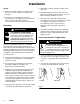
Installation NOTES: D Reference numbers and letters in parentheses in the text refer to the callouts in the figures and drawings. D Accessories are available from your Graco representative. If you supply your own accessories, be sure they are adequately sized and pressure-rated to meet the system’s requirements. Grounding WARNING FIRE AND EXPLOSION HAZARD To reduce the risk of fire, explosion, and serious injury, proper electrical grounding of every part of your system is essential.
Installation Connections Machine Mount Valve D The fluid inlet is 1/4 npt(f). Install a remote 4-way air control valve to operate the valve. Connect an open air signal air line to the 1/8 npt(f) OPEN port. Connect a close air signal air line to the 1/8 npt(f) CLOSE port. D The fluid outlet is 1/4 npt(f) or 3/4–16 unf(m). D Air inlets are 1/8 npt(f). Air Switch Hand Held Valve D See Accessories, page 25, to order air control valves and tubing.
Operation WARNING COMPONENT RUPTURE HAZARD To reduce the risk of over-pressurization, which can cause component rupture and serious injury, never exceed 3000 psi (21 MPa, 207 bar) fluid pressure, or 120 psi (0.84 MPa, 8.4 bar) air pressure to the valve. Pressure Relief Procedure WARNING SKIN INJECTION HAZARD The system pressure must be manually relieved to prevent the system from starting or spraying accidentally. Fluid under high pressure can be injected through the skin and cause serious injury.
Operation Air Switch Hand Held Valve D The valve is at full stroke when the hex nut (44) is at the end of the adjustment shaft (42). The valve operation is such that there are only two valve conditions: either fully open or fully closed. D The valve is opened and closed by the internal air control valve. Trigger the gun to open the valve. Release the trigger to close the valve. Adjusting the nut (44) on the shaft (42) towards the valve, or clockwise, will reduce the stroke length.
Troubleshooting WARNING SKIN INJECTION HAZARD To reduce the risk of serious injury whenever you are instructed to relieve pressure, always follow the Pressure Relief Procedure on page 8. 1. Relieve the pressure. 2. Check all possible causes to the problem before disassembling the pump. PROBLEM CAUSE SOLUTION Valve does not open Insufficient air pressure Turn on or turn up air pressure. Air not exhausted from behind air cylin- Use four-way, relieving-type air valve operator.
Service (Models 965766, 965767, 965768, and 965786 only) WARNING SKIN INJECTION HAZARD To reduce the risk of serious injury whenever you are instructed to relieve pressure, always follow the Pressure Relief Procedure on page 8. Disassembly 1. Relieve all air and fluid pressure. 2. Disconnect the valve from the system. 3. Remove the four nosepiece screws (15), and pull the nosepiece (40) away from the valve. Remove the snuff-back ring (41). See Fig. 5, page 14. 12.
Service (Models 965766, 965767, 965768, and 965786 only) Reassembly Air Cylinder Section 1. Lubricate the shaft o-rings (4) and the bearings (5) with grease supplied in the repair kit. Insert o-rings into the air cylinder (1) and air cap (11) cavities. See Fig. 5. 2. Press the bearings (5) flush into the air cylinder housing and air cap, trapping the o-rings (4). 3. Lubricate and reassemble the piston assembly; piston (10), o-ring (9), dowel pin (7), adjustment shaft (42), o-ring (6), and shaft (3).
Service (Models 965766, 965767, 965768, and 965786 only) Air Valve (if equipped) 1. Insert the spring (51) into the housing (50). 2. Lubricate and install an o-ring (46) into the housing. 8. Orient the gasket (30) to the holes on the air cylinder (1). Screw the air valve assembly to the cylinder with the screws (60) and lock-washers (61). TIghten the screws evenly to 15–20 in-lbs (1.7–2.2 NSm). 3. Install a spacer (52), internal bevel first, into the housing. 9.
Service (Models 965766, 965767, 965768, and 965786 only) 1 4 47 4 4 46 48 4 5 49 58 59 8370A 2 60 61 53 51 52 4 4 57 50 56 6 54 8375B 4 55 4 11 12 13, 14 6 4 4 4 4 4 7 5 4 3 B 28, 29 20 21 22 39 27 2 7 23 3 8 40 15 A 44 42 1 2 4 7 9 4 10 30 19 18 16 4 4 26 38 25 5 Tighten to 60–70 in-lbs (6.8–7.9 NSm). 6 Screw the bushing (53) to the housing (50) with screw (54). Tighten to 140–150 in-lbs (15.8–16.9 NSm).
Notes 308876 15
Parts (Models 965766, 965767, 965768, and 965786 only) 30 15 12 42 44 43 11 2 1 (965766 & 965786 only) 9 10 6 7 5 19 4 18 3 28, 29 16 38 20 21 22 26 25 41 39 27 23 40 15 8371A 16 308876
Parts Model 965766 Model 243482 Machine Mount Valve Stainless steel wetted parts Orbiter Mounted Valve Stainless steel wetted parts Model 965786 Model 243666 Automatic Machine Mount Valve Aluminum wetted parts PrecisionFlo Control Valve Stainless steel wetted parts Ref. No. 1 2 3 4* 5* 6* 7* 9* 10 11 Part No.
Parts 63 (965768 only) 60 61 53 56 54 8375B 8370A 55 (965767 only) 47 46 48 51 49 58 52 57 59 50 8372A 18 308876
Service (Models 243482 and 243666 only) WARNING SKIN INJECTION HAZARD To reduce the risk of serious injury whenever you are instructed to relieve pressure, always follow the Pressure Relief Procedure on page 8. Disassembly 1. Relieve all air and fluid pressure. 2. Disconnect the valve from the system. 3. Remove the four nosepiece screws (15), and pull the nosepiece (40) away from the valve. Remove the snuff-back ring (41). See Fig. 5, page 14. 4. Use an 1/8 in.
Service (Models 243482 and 243666 only) Reassembly Air Cylinder Section 1. Lubricate the shaft o-rings (4) and the bearings (5) with grease supplied in the repair kit. Insert o-rings into the air cylinder (1) and air cap (11) cavities. See Fig. 5. 2. Press the bearings (5) flush into the air cylinder housing and air cap, trapping the o-rings (4). 3. Lubricate and reassemble the piston assembly; piston (10), o-ring (9), dowel pin (7), o-ring (6), and shaft (3). Tighten the jam nut (45) to 15–20 in-lb (1.7–2.
Parts (Models 243482 and 243666 only) 2 2 12 13, 14 6 2 2 2 2 2 7 5 4 3 28, 29 20 21 22 39 3 4 27 23 1 4 40 15 15 40 45 2 9 2 10 30 2 19 18 16 2 26 38 25 2 1 Tighten oppositely and evenly to 40–45 in-lbs (4.5–5 NSm). 2 Lubricate with grease supplied in the repair kit. 3 Tighten to 15–20 in lbs (17–22 NSm) 4 Apply Loctite Primer N7649 and Loctite TL242, 243, or equivalent (“blue” Loctite). Model 243482 Fig.
Parts (Models 243482 and 243666 only) 30 15 12 19 1 45 6 9 7 10 5 19 4 18 3 28, 29 16 20 21 38 22 26 25 39 41 27 23 40 31 40 31 Model 243482 8371A 22 308876
Parts Model 965767 Hand Held Valve with Pneumatic Trigger Aluminum wetted parts See page 16 for illustration of items 1–44. See page 18 for illustration of items 46–62. Ref. No. 1 3 4* 5* 6* 7* 9* 10 11 12 13 14 16*† Part No.
Parts Model 965768 Hand Held Valve with Electric Switch Aluminum wetted parts See page 16 for illustration of items 1–44. See page 18 for illustration of items 53–63. Ref. No. 1 3 4* 5* 6* 7* 9* 10 11 12 14 15 16*† Part No.
Accessories Plastic Tube Fittings to Connect Air Signals Tube OD 1/8 NPT (M) Straight 1/8 NPT (M) 90º Swivel Tube Tee 1/8 in. 5/32 in. 1/4 in. 598329 104172 513826 598140 597151 551203 514435 111167 Tube OD 1/4 NPT (M) Straight 1/4 NPT (M) 90º Swivel 5/32 in. 1/4 in. 598252 104165 598327 C19391 Plastic Tubing for Air Signal Lines Part No. Description 513063 514607 C12509 1/8 in. O.D. Nylon 5/32 in. O.D. Nylon 1/4 in. O.D.
Accessories Fluid Nozzles 168683 Nozzle Bushing Zinc-plated steel nozzles, 1/8 npt* Zinc-plated steel, 1/8 npt Kits Part No. Orifice 607665 0.125 in. (3.17 mm) 2 in. (51 mm) 949631 Conversion Kit 161505 0.09 in. (2.28 mm) 164799 0.055 in. (1.39 mm) 2-1/8 in. (54 mm) Pneumatic 4–way valve with housing, handle, and trigger and other parts necessary to convert 965766 or 965786 to a hand held valve. * Length 2 in. (51 mm) Requires a 1/8 npt(f) bushing. Order 168683 Nozzle Bushing.
Technical Data Category Data Maximum Fluid Pressure 4000 psi (28 MPa, 276 bar) Maximum Cylinder Air Pressure 120 psi (0.84 MPa, 8.4 bar) Air inlets (open and close ports) 1/8 npt(f) Fluid Inlet 1/4 npt(f) Fluid Outlet 1/4 npt(f) and 3/4–16 unf(m) Fluid Viscosity Range 20 cps to 1 million cps Snuffer Action Fluid Section Isolation chamber with zerk fittings Divorced Air Cylinder Piston cylinder, EP o-rings Weight Aluminum Valve Stainless Steel Valve Handle Kit 1.43 lb (0.65 kg) 2.07 lb (0.
Dimensions 2.25 in. (57.15 mm) 1.75 in. (44.45 mm) 0.88 in. (22.35 mm) 1.75 in. (44.45 mm) 6.13 in. (155.7 mm) 3.5 in. (88.9 mm) 1.63 in. (41.4 mm) 1.42 in. (36.07 mm) 5 in. (127 mm) 2.25 in. (57.
Notes 308876 29
Graco Standard Warranty Graco warrants all equipment manufactured by Graco and bearing its name to be free from defects in material and workmanship on the date of sale to the original purchaser for use. With the exception of any special, extended, or limited warranty published by Graco, Graco will, for a period of twelve months from the date of sale, repair or replace any part of the equipment determined by Graco to be defective.