Instructions/Parts List High Pressure Fluid Regulators 309475F Important Safety Instructions Read all warnings and instructions in this manual. Save these instructions.
Contents List of Models . . . . . . . . . . . . . . . . . . . . . . . . . . . . . 3 Introduction . . . . . . . . . . . . . . . . . . . . . . . . . . . . . . . 6 Installation . . . . . . . . . . . . . . . . . . . . . . . . . . . . . . . . 8 Operation . . . . . . . . . . . . . . . . . . . . . . . . . . . . . . . . 13 Flush Before First Use . . . . . . . . . . . . . . . . . . . 13 Pressure Relief Procedure . . . . . . . . . . . . . . . . 13 Adjusting the Regulator . . . . . . . . . . . . . . . . . . .
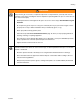
List of Models List of Models Part No. Series Model Type Maximum Fluid Inlet Pressure Regulated Pressure Range 233760 234266 B B P60-VP DN7 P60-VP DN7 npt Pneumatic 5000 psi (36 MPa, 360 bar) 70-900 psi (0.
Warning WARNING EQUIPMENT MISUSE HAZARD Equipment misuse can cause the equipment to rupture or malfunction and result in serious injury. 4 • This equipment is for professional use only. • Read all instruction manuals, tags, and labels before operating the equipment. • Use the equipment only for its intended purpose. If you are not sure, call your Graco distributor. • Do not alter or modify this equipment. Use only genuine Graco parts and accessories. • Check equipment daily.
Warning WARNING SKIN INJECTION HAZARD Spray from the gun, hose leaks, or ruptured components can inject fluid into your body and cause an extremely serious injury, including the need for amputation. Splashing fluid in the eyes or on the skin can also cause serious injury. • Fluid injected into the skin might look like just a cut, but is a serious injury. Get immediate surgical treatment. • Do not point the gun at anyone or at any part of the body. Do not put your hand or fingers over the spray tip.
Introduction Introduction A fluid pressure regulator is used in air-assisted spray systems to ensure accurate, positive control of fluid pressure to a spray gun, dispensing valve, or atomizing head. Models 233767, 233814, 233768, 234260, 234264, and 234265 (FIG. 2.) are mechanically operated fluid pressure regulators designed primarily for use with low to medium viscosity fluids.
Introduction Adjustment knob Spring Valve plunger Fluid inlet (from pump) Fluid outlet (to gun) A9671IT TI1769A Fig. 2. Cutaway of Mechanical Fluid Pressure Regulator Air Inlet Diaphragm Valve plunger Fluid Outlet (To gun) Fluid Inlet (From pump) TI1774A Fig. 3.
Installation Installation 1. Install one regulator for each spray gun. 2. Apply thread sealant to connections as necessary. 3. Make sure that the direction of fluid flow agrees with the flow direction markings on the regulator body. a. Install a fluid pressure regulator upstream of the gun: Connect the fluid line from the pump to the inlet of the fluid regulator. Connect the fluid line to the gun to the regulator’s outlet. 8 b. Install a back pressure regulator downstream of the gun.
Installation B A L F C Air in to pump D Air in to gun H Y B H E K Z M G G Fluid J Fluid in TI1763C Fig. 4.
Installation A A B L N C Air to Pump Air to Fluid Regulator D B F Air to Gun B E Y K Z Fluid H M J G F lu id G TI1764C Fig. 5.
Installation B Air supply D H A Air to gun Fluid in to gun L J P H TI1765A Fig. 6.
Installation 12 309475F
Operation Operation Flush Before First Use Adjusting the Regulator Your pressure regulator has been tested in the factory with an anti-corrosion liquid. Before using the regulator, thoroughly flush the system with a solvent to remove residue of this liquid as well as any contaminants that have been introduced during assembly of the system. The fluid pressure regulator controls pressure downstream from its outlet. The inlet fluid pressure should always be higher than the outlet fluid pressure.
Troubleshooting Troubleshooting Relieve the pressure (page 13) before checking or repairing the equipment. To repair the regulator, refer to page 15. Problem Drop in fluid outlet pressure. Cause Solution Ruptured diaphragm (17) (pneumatic regulators only). Replace diaphragm. Air escaping (pneumatic regulators only). Check air hose and connections. Replace packings (13). Worn packings. Replace packings (13). Fluid outlet pressure increases to level of fluid inlet pressure.
Maintenance Maintenance Flushing WARNING Do not allow paint or solvent to sit in the system for extended periods. Fluid could dry on the plunger and cause leakage at the plunger packings. If leakage occurs, disassemble and clean the regulator. Cleaning and Repair The system pressure must be manually relieved to prevent the system from starting or spraying accidentally. Fluid under high pressure can be injected through the skin and cause serious injury.
Parts Parts Mechanical Regulators Part Nos. 233767 (shown), 233768, 233814, 234260, 234264, and 234265 26 26 14 24 13 12 23 15 21 9 1 1 20 6 25 4 16 5 8 19 7 27 3 16 2 10 11 16 1 Torque to 25 N•m (18.5 ft-lb).
Parts Mechanical Regulators Part Nos. 233767 (shown), 233768, 233814, 234260, 234264, and 234265 Ref. No. Part No. 1 Description Qty Part No.
Parts Mechanical Back Pressure Regulators Part Nos. 233771, 233772, 234268, and 234269 (shown) 26 10 26 11 24 14 23 13 12 21 15 9 1 20 1 25 6 4 16 5 27 19 2 16 1 18 Torque to 25 N•m (18.5 ft-lb).
Parts Mechanical Back Pressure Regulators Part Nos. 233771, 233772, 234268, and 234269 Ref. No. Part No. 1 Description Qty Ref. No. Part No.
Parts Pneumatic Regulators Part No. 233813 and 234259 1 26 Torque to 10 N•m (7.5 ft-lb).
Parts Pneumatic Regulators Part No. 233813 and 234259 Ref. No. Part No. 1 Description HOUSING, lower 1 HOUSING, lower (npt version only) 1 1 1 1 1 1 1 1 1 1 2 15A238 PLUG, screw 3 117089 SPRING, compression 4 245367 SEAT, valve 5 15Y030 O-RING 6 15Y031 O-RING 7 15A206 SUPPORT, ball 8 117104 BALL, 5mm, carbide 9 245375 PLUNGER, valve 11 15Y033 O-RING 309475F Qty Ref. No. Part No.
Parts Pneumatic Regulators Part Nos. 233760 (shown), 233769, 233770, 234266, 234270, and 234271 26 1 1 Torque to 10 N•m (7.5 ft-lb). 2 Torque to 12 N•m (8.8 ft-lb).
Parts Pneumatic Regulators Part Nos. 233760 (shown), 233769, 233770, 234266, 234270, and 234271 Ref. No. Part No.
Technical Data Technical Data Category Maximum Fluid Inlet Pressure (Fluid Pressure Regulators) Data 233814, 234260: 2600 psi (18 MPa, 180 bar) 233760, 233767, 233768, 233769, 233770, 233813, 234259, 234264, 234265, 234266, 234270, and 234271: 5000 psi (36 MPa, 360 bar) Maximum Permanent Supply 233771, 234268: 2500 psi (17 MPa, 170 bar) Pressure (Back Pressure Regulators) 233772, 234269: 3400 psi (23.5 MPa, 235 bar) Pressure Range 233760, 234266: 70-900 psi (0.
Accessory Gauges Accessory Gauges Model 233760 234266 233769 234270 234770 234271 309475F Gauge 118340 118340 118341 118341 118341 118341 25
Flow Rate Data Flow Rate Data Maximum fluid flow with 10 weight oil, regulator wide open and no downstream restrictions. Part No.
Mounting Dimensions 309475F 27
Graco Warranty Graco warrants all equipment referenced in this document which is manufactured by Graco and bearing its name to be free from defects in material and workmanship on the date of sale to the original purchaser for use. With the exception of any special, extended, or limited warranty published by Graco, Graco will, for a period of twelve months from the date of sale, repair or replace any part of the equipment determined by Graco to be defective.