Repair GH™ 833 Sprayers 311283D ENG Korean patent: 10-0647761 - Use with Architectural Coatings, Paints, Roof Coatings and Below Grade Coatings 4000 psi (27.6 MPa, 275.8 bar) Maximum Working Pressure Important Safety Instructions. Read all warnings and instructions in this manual. Save these instructions. Model: 249318, 249617, 253471, 253472 Related Manuals 311279 311484 311485 311254 ti7107b Graco Inc. P.O. Box 1441 Minneapolis, MN 55440-1441 Copyright 2006, Graco Inc. is registered to I.S.
Warning Warning The following are general warning related to the safe setup, use, grounding, maintenance and repair of this equipment. Additional, more specific warnings may be found throughout the body of this manual where applicable. Symbols appearing in the body of the manual refer to these general warnings. When these symbols appear throughout the manual, refer back to these pages for a description of the specific hazard.
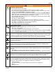
Warning WARNING EQUIPMENT MISUSE HAZARD Misuse can cause death or serious injury. • Do not operate the unit when fatigued or under the influence of drugs or alcohol. • Do not exceed the maximum working pressure or temperature rating of the lowest rated system component. See Technical Data in all equipment manuals. • Use fluids and solvents that are compatible with equipment wetted parts. See Technical Data in all equipment manuals. Read fluid and solvent manufacturer’s warnings.
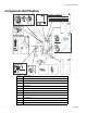
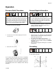
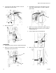
Component Identification Component Identification , 2 1 8 11 3 4 9 ti7107b 6 10 ti7133b 5 Ref 4 ti7133 7 Description 1 Hydraulic pump valve 2 Pressure control 3 Lock ring 4 Drain valve 5 Engine ON/OFF switch 6 Engine controls 7 Trigger lock 8 Serial number ID label 9 Lift locations 10 Suction holder 11 Hydraulic oil fill 311283D
Operation Operation Pressure Relief Procedure System pressure must be manually relieved to prevent it from starting or spraying accidentally. Fluid under high pressure can be injected into the skin and cause serious injury. To reduce risk of injury from injection, follow this procedure whenever you are instructed to relieve pressure, stop spraying, service equipment or install or clean spray tip. Read warnings, page 4. General Repair Information • • 1 Set pump valve OFF. Turn engine OFF.
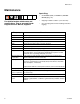
Maintenance Maintenance Spark Plug: For detailed engine maintenance and specifications, refer to separate Honda Engines Owner’s Manual, supplied. Frequency • Use BPR6ES (NGK) or W20EPR-U (NIPPONDENSO) plug, only. • Gap plug to 0.028 to 0.031 in. (0.7 to 0.8 mm). • Use spark plug wrench when installing and removing plug. Procedure Daily Check engine oil level and fill as necessary. Daily Check hydraulic oil level and fill as necessary. Daily Check hose for wear and damage.
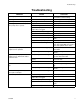
Troubleshooting Troubleshooting PROBLEM CAUSE SOLUTION Gas engine pulls hard (won't start) Hydraulic pressure is too high Turn hydraulic pressure knob counterclockwise to lowest setting Gas engine does not start Switch OFF, low oil, no gasoline Consult engine manual, supplied Gas engine doesn't work properly Faulty engine Consult engine manual, supplied Gas engine operates, but displacement pump doesn't operate Pump valve is OFF Set pump valve ON Pressure setting too low Increase pressure
Troubleshooting PROBLEM CAUSE SOLUTION The sprayer overheats Paint buildup on hydraulic components Oil level is low Fill with oil. Spitting from gun Air in fluid pump or hose Check for loose connections on siphon assembly, tighten, then reprime pump. Loose intake suction Tighten. Fluid supply is low or empty Refill supply container. Low hydraulic fluid level Turn sprayer OFF. Add fluid*. Excessive hydraulic pump noise Clean *Check hydraulic fluid level often.
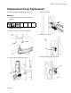
Displacement Pump Replacement Displacement Pump Replacement See manual 311485 for pump repair instructions. 5. Remove clip (121). Removal 1. Flush pump (36). Stop pump on down stroke if possible. 121 2. Relieve pressure, page 5. 3. Remove suction set (147) from pump (36). ti7789 6. Slide cover up (124). 36 124 147 ti7816 7. Separate coupling (125) and remove. 4. Remove filter housing (110), page 15.
Displacement Pump Replacement 8. Loosen jam nut (122) with a hammer. Unscrew pump (36) from power head. 3. Hand tighten jam nut (122). Then tighten securely 1/8 to 1/4 turn with hammer or torque to 330 ft-lb (447.4 N•m). 122 122 36 ti7782 9. Remove pump (36). ti7817 4. Slide cover (124) up over pump rod. With engine in OFF position, pull recoil starter to move rod until it contacts pump rod. 5. Install coupling (125) around pump rod. 125 36 ti7804 Installation ti7771 1.
Displacement Pump Replacement 7. Install clip pin (121) to secure. 8. Install filter housing (110), page 15. 110 121 125 ti7809 ti7772 9. Connect suction hose (147) to pump outlet (36).
Pump Power Head Replacement Pump Power Head Replacement Removal 4. Remove power head from unit. 1. Relieve pressure, page 5. 2. Remove hydraulic lines (100, 101) from head (75). 100 101 75 ti7847 Installation 1. Install power head on unit. ti7803 3. Loosen (4) mounting bolts (7) on the adapter enough to lift and remove assembly.
Pump Power Head Replacement 2. Tighten power head bolts (7). Torque bolts to 400 + 10 in-lb (45 + 1 N•m). ti7853 3. Attach hoses (100, 101) to head (75). Torque to 450 + 10 in-lb (50.84 N•m). 101 100 75 ti7777 4. To purge air from hydraulic lines, increase pressure enough to start hydraulic motor stroking and allow fluid to circulate for 15 seconds.Turn pressure down. Turn prime valve horizontal (closed).
Hydraulic Motor Hydraulic Motor 2 1 450 in-lb (51 N.m) 2 600 in-lb (68 N.m) 3 60 in-lb (7 N.m) 4 930 in-lb (105 N.
Filter Housing Replacement Filter Housing Replacement Installation 1. Install filter housing (110) in pump opening. Removal 1. Relieve pressure, page 5. 2. Remove paint and drain lines from filter housing. 110 ti7772 2. Tighten fitting. ti7845 3. Attach paint and drain lines. 3. Loosen filter housing fitting (110) until housing and remove housing from pump. ti7850 ti7119 Torque to 225 + 10 in-lb. (25.4+ 1.1 N.
Hydraulic Pump Replacement Hydraulic Pump Replacement Changing Hydraulic Oil Draining Oil a. Place drain pan under oil tank and drain plug. b. Unscrew reservoir (64) drain plug and drain oil from reservoir. 3. Remove screw (197) and pump handle cover (196). Remove four cover bolts (79) and cover (140). (It is not necessary to remove the hydraulic lines before removing cover. The cover is designed to provide ample room for the cover to fit over the hose.) 196 197 79 140 ti7805b drain plug 4.
Hydraulic Pump Replacement 5. Remove (4) belt cover screws (79), washers (78) and grommets (80) (2 each side). 7. Remove belt (19), page 20. 8. Loosen set-screws (87) on front of large pulley (4). 80 78 4 79 87 67 ti7796 6. Remove belt cover (67). 67 ti7783 9. Remove pulley (4) from hydraulic pump shaft. 4 ti7807 ti7795 10. Remove nuts (10) and screws (9) holding pump to frame.
Hydraulic Pump Replacement 2. Install new pump (3) in frame. 11. Remove hydraulic pump (3). 3. Install screws (9) and nuts (10). Torque to 225 + 10 in-lb (25.42 N.m). 3 3 9 ti7800 12. Remove fittings (30, 34, 35) from pump (3) and set aside to use on the new pump. 10 34 ( ti7778 3 4. Replace large pulley (4) on hydraulic pump shaft. 35 4 ti7816 30 Installation 1. Install fittings (30, 34, 35) from old pump on new pump. Torque fitting 30 and 35 to 600 + 10 in-lb (67.8 N.m).
Hydraulic Pump Replacement 6. Replace set-screws (87). Tighten and torque to 60 + 2 in-lb (6.8 + 0.2 N•m). NOTE: Tighten set-screw on shaft before tightening set-screw on pump shaft. 7. Position belt (19) over pulleys (4, 6); Installing Belt, page 20. 9. Install suction lines. Tighten fittings. Torque fitting A to 225 + 10 in-lb (25.4 + 1.1 N.m). Fitting B to 450 +10 in-lb (50.1 + 1.1. N.m). Fitting C to 225 in-lb (25.4 N.m). A B 8.
Hydraulic Pump Replacement Belt Removal and Replacement (recommended method) Removing Belt Installing Belt a. Put belt over lower pulley (6) and align correctly. b. Line up belt over top left side of large pulley (4). a. Place a ziptie around belt (19). 19 ziptie ti7869 ti7843 c. Moving parts can pinch or amputate fingers and other body parts. To avoid serious injury be sure engine is in OFF position before pulling engine recoil. b.
Hydraulic Pump Replacement Alternate Belt Removal and Installation b. Tighten engine bolts (21). Torque to 225 + 10 in-lb (25.4 + 1.1 N.m). c. Check belt (19) alignment on both large (4) and small pulley (6). When properly positioned over pulleys, belt should be centered on pulleys and completely over all grooves. Removing Belt a. Loosen engine bolts (21) to relieve tension on belt. b. Slide belt off pulleys. Installing Belt a. Install belt (19) over small (6) and large (4) pulleys.
Hydraulic Pump Replacement Replacing Oil Reservoir Removal 4. Loosen and remove suction hose (153). 1. Relieve pressure, page 5. 32 2. Drain oil from reservoir (64) following Draining Oil procedure, page 16. Keep plug for use on new reservoir. 153 ti7785 5. Remove and keep suction fitting (32) for use on new reservoir. 6. Loosen and remove return lines (100, 101). Drain Plug 100 ti 7784 101 3. Remove fill cap (27) and filter assembly (111). Keep for use on new reservoir. 111 27 ti7785 ti7803 7.
Hydraulic Pump Replacement 9. Lift reservoir (64) out of frame. 64 ti7791 8. Remove (2) top bolts (86) and 2 bottom nuts (84) securing reservoir (64) to frame. ti7806 Installation 1. Install plug (102), return elbow (31), suction fitting (32), inlet screen (89) and filter assembly (111) in new reservoir (64).
Hydraulic Pump Replacement 5. Reattach return lines (100, 101). Torque to 450 + 10 in-lb (51 + 1.1 N•m). 2. Install new reservoir (64) in frame. 64 100 101 ti7781 3. Replace bolts (86) and nuts (84). Tighten bolts. Torque to 125 + 10 in-lb 14 + 1.1 N•m). 4. Connect coolant line to reservoir (64). Torque to 225 in-lb (14.1 N.m). ti7777 6. Reattach suction hose (153). Toque to 600 + 10 in-lb (68 + 1.1 N•m).
Hydraulic Pump Replacement 7. Verify drain plug has been replaced. Fill oil reservoir with oil to high mark on dip stick (approximately 3.5 gallons). ti7784 Drain Plug 8. Replace cap (27).
Changing Hydraulic Fluid Filter Changing Hydraulic Fluid Filter Removal Installation 1. Install new o-ring (113) from kit. 2. Install new filter (108) over cap (155). 1. Relieve pressure, page 5. 2. Loosen and remove hose (101) from fitting (103). 3. Remove filter housing (111) from reservoir (64). 4. Remove bottom filer cap (155) from housing (111). 5. Pull filter (108) off cap (155). 3. Install cap (155) and filter (108) in filter housing (111). Hand tighten cap till snug.
Cooler Replacement Cooler Replacement 4. Remove screws (79), washers (78) and support bar (77) from cooling coil (72). 72 Removal 1. Relieve pressure, page 5. 77 2. Loosen ground screw and remove ground clamp (95) from sprayer. 79 78 ti7794 5. Remove coil (72) from sprayer frame. 95 ti7799 3. Loosen and remove return line to oil tank and hydraulic line to cooler.
Cooler Replacement Installation 1. Install new coil (72). Replace support bar (77), washers (78) and screws (79). Tighten screws. 3. Replace ground wire (95) and tighten screw. Torque to 25-30 in-lbs (2.8 - 3.4 N.m). 95 72 ti7774 ti776 8 2. Reconnect return line to oil tank and hydraulic line to cooler. Torque to 225 in-lb (25.4 N.m). 4. Replace bar and screws. Torque to 25-30 in-lb (2.8-3.4 N.m).
Motor Replacement Motor Replacement Removing Pulley (6) NOTE: This procedure is only necessary if you are replacing the motor. When you install a new motor you reuse the existing pulley. Removal 1. Relieve pressure, page 5. 2. Remove screws (79) and washers (78) and belt cover (67). Removal a. Loosen set screw (87) located on the side of the pulley (6). b. Remove large bolt (24) in the center of pulley (6). c. Pull pulley (6) off motor (5). 3. Remove belt (19), page 20. 4.
Motor Replacement 67 4 79 78 19 87 86 14 5 80 21 6 65 24 10 ti7797 70 30 311283D
Removing Handle Removing Handle 3. Remove frame tube plugs (120) located behind the wheels. Fixed Mounting (optional) To prevent damaging the unit when transporting it in a truck or on a trailer, Graco recommends fixed mounting to the vehicle. 120 Repositioning Handle Before you can secure the unit to a truck or trailer bed, you must reposition the handle. 4. Insert plugs (120) in upper frame handle tubes (a). (a) 1. Remove the 4 handle sleeve screws (143). 143 120 5.
Removing Handle Securing Unit to Vehicle Bed For fixed mounting, fasten U-bolts over sprayer frame as indicated in the following illustration. 2. Place U-bolts over sprayer frame and through holes in vehicle bed. Place a washer and nut over bolt end. Using a wrench, tighten nut securely. 1. Reposition handle, steps 1-5, page 31.
Technical Data Technical Data Sprayer Hydraulic Pressure psi (bar) Hydraulic Reservoir Capacity Gallon (liters) Motor HP (kW) Maximum Delivery gpm (lpm) Maximum Tip Size • 1 gun • 2 guns • 3 guns • 4 guns • 5 guns • 6 guns Fluid Inlet inches Fluid Outlet inches GH833 Gas 2750 (19.0) 4.0 (15.1) Honda 13 (9.7) 4.0 (15.1) .065 .046 .037 .032 .028 .026 1-1/2 to 11-1/2 NPT (m) 1 to 11-1/2 NPT (f) Dimensions Weight lb (kg) Height inch (cm) Width inch (cm) Length inch (cm) 360 (163) 40 (101.6) 27 (68.
Warranty Warranty Graco warrants all equipment referenced in this document which is manufactured by Graco and bearing its name to be free from defects in material and workmanship on the date of sale to the original purchaser for use. With the exception of any special, extended, or limited warranty published by Graco, Graco will, for a period of twelve months from the date of sale, repair or replace any part of the equipment determined by Graco to be defective.