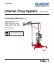
Operation Internal Chop System Low Emission Internal-Mix Gel-Coat For use with Polyester Resin, and Gel-Coat Maximum fluid working pressure by Fluid Section Assembly: 20864-05 - 1300 psi. (9 MPa, 90 bar) 21780-01 - 1700 psi. (12 MPa, 117 bar) 22026-01 - 2000 psi. (14 MPa, 138 bar) Maximum air pressure: 100 psi. (0.7 MPa, 7 bar) Important Safety Instructions Read all warnings and instructions in this manual. Save these instructions.
Contents Warnings Warnings ............................................................................................................................................................ Important Safety Information ............................................................................................................................. Grounding ..........................................................................................................................................................
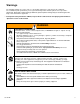
9CTPKPIU The following warnings are for the setup, use, grounding, maintenance, and repair of this equipment. The exclamation point symbol alerts you to a general warning and the hazard symbol refers to procedure VSHFL¿F ULVN 5HIHU EDFN WR WKHVH ZDUQLQJV $GGLWLRQDO SURGXFW VSHFL¿F ZDUQLQJV PD\ EH IRXQG WKURXJKRXW WKH body of this manual where applicable. • See Important Safety Information - MEKP, Polyester Resins and Gel-Coats and Spraying and Lamination Operations section of this manual.
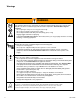
Warnings 9#40+0) SKIN INJECTION HAZARD +LJK SUHVVXUH ÀXLG IURP JXQ KRVH OHDNV RU UXSWXUHG FRPSRQHQWV ZLOO SLHUFH VNLQ 7KLV PD\ ORRN OLNH MXVW D FXW EXW LW LV D VHULRXV LQMXU\ WKDW FDQ UHVXOW LQ DPSXWDWLRQ Get immediate surgical treatment. • Do not point gun at anyone or at any part of the body. • Do not put your hand over the dispense outlet.
Important Safety Information Methyl Ethyl Ketone Peroxide (MEKP) MEKP is among the more hazardous materials found in commercial channels. Proper handling of the “unstable (reactive)” chemicals presents a GH¿QLWH FKDOOHQJH WR WKH SODVWLFV LQGXVWU\ 7KH KLJKO\ UHDFWLYH SURSHUW\ ZKLFK PDNHV 0(.
Grounding This equipment needs to be grounded. Ground the spray gun through connection to a *ODV&UDIW DSSURYHG JURXQGHG ÀXLG VXSSO\ KRVH &KHFN \RXU ORFDO HOHFWULFDO FRGH DQG UHODWHG PDQXDOV for detailed grounding instructions of all equipment in WKH ZRUN DUHD A grounding wire and clamp are provided, assembly p/n 17440-00 with all FRP equipment.
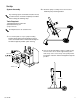
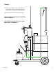
Set-Up 6\VWHP $VVHPEO\ 2. a. Stand the pump assembly next to the mast and LQVWDOO WKH SXPS PRXQWLQJ EUDFNHW $Q\ PRXQWLQJ RSWLRQ FDUW PDVW ERRP ÀRRU PRXQW or wall mount etc. should be completely assembled before starting the following steps. Tools Required: 6WDQGDUG ZUHQFK VRFNHW VHW 6WDQGDUG KH[ NH\ VHW 3) Tape measure All “Required tools” are standard sizes. 1.
Set-Up 3. Attach air manifold p/n 23555-00 to the air motor. 5. ,QVWDOO WKH FDWDO\VW MXJ ZLWK WKH HOERZ ¿WWLQJ IDFLQJ WKH front of the unit. 4. 0RXQW FDWDO\VW ERWWOH EUDFNHW ZLWK VXSSOLHG X EROWV p/n CP-126, 34in. from the top of the cart, to the top RI WKH FDWDO\VW EUDFNHW DQG SDUDOOHO ZLWK WKH PDWHULDO pump. 6.
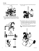
Set-Up 7. Remove the pump inlet saftey cap and drain the testing oil into an open container. Attach green SLFN XS KRVH WR WKH SXPS LQOHW ¿WWLQJ DQG WLJKWHQ 8. $WWDFK JUHHQ SLFN XS KRVH WR WKH SLFN XS WXEH 8. FOR INDY CHOPPER GUN INSTALLATION BEGIN STEPS 9 THROUGH 13 . FOR FORMULA CHOPPER GUN INSTALLATION BEGIN STEPS 14 THROUGH 18. 7.
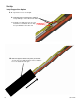
Set-Up Indy Chopper Gun Option 9. a. Lay all of the hoses out straight. E ,QVWDOO ¿WWLQJV S Q¶V DQG using PTFE tape on the NPT threads ONLY. c. Install the assembly from step “b” to the material hose and attach the 3 ft. whip hose p/n H42503 to the other end. 10. 6OLGH WKH VXSSOLHG ³EODFN VFXII MDFNHW´ S Q )0 over the hose assembly and leave it loose until the hoses are attached to the gun.
Set-Up 11. a. Attach the hoses to the gun. E group the hoses together as shown and wrap them with tape about every 2 feet. c.
Set-Up Secure the four hoses to WKH ERRP ZLWK ELQGLQJ VWUDSV S Q See Detail C 5RXWH WKH IRXU KRVHV EHWZHHQ the two springs. Secure the four hoses to WKH ERRP ZLWK ELQGLQJ VWUDSV S Q 12.
Set-Up 13. Attach the hoses to the unit as shown. TO BOOM Clear Tubing 1/4 in. Stainless Catalyst Hose Red Air Hose Red Solvent Air Tubing Clear Tubing 1/8 in. Place decal here Clear Tubing 3/8 in.
Set-Up Formula Chopper Gun Option 14. a. Lay all of the hoses and trigger air tubing out straight. E ,QVWDOO ¿WWLQJV S Q¶V DQG using PTFE tape on the NPT threads ONLY. c. Install the assembly from step “B” to the material hose and attach the 3 ft. whip hose p/n H42503 to the other end. 15. 6OLGH WKH VXSSOLHG ³EODFN VFXII MDFNHW´ S Q )0 over the hose assembly and leave it loose until the hoses are attached to the gun.
Set-Up Yellow Solvent Hose p/n 236 Red Chopper Air Hose p/n 17798-25 16. a. Attach the hoses to the gun. E Group the hoses together as shown and wrap them with tape about every 2 feet. c.
Set-Up 6HFXUH WKH ¿YH KRVHV WR WKH ERRP ZLWK ELQGLQJ VWUDSV S Q See Detail C 5RXWH WKH ¿YH KRVHV EHWZHHQ the two springs. 6HFXUH WKH ¿YH KRVHV WR WKH ERRP ZLWK ELQGLQJ VWUDSV S Q 17.
Set-Up 18. Attach the hoses to the unit as shown. TO BOOM Clear Tubing 1/4 in. Stainless Catalyst Hose Red Air Hose Red Solvent Air Tubing Clear Tubing 1/8 in. Place decal here Trigger Air Clear Tubing Remove plug and install elbow ¿WWLQJ S Q Clear Tubing 3/8 in.
Set-Up SSP-175 Safety Guard Kit SSP-175 18 Part 1XPEHU Description Qty.
Pressure Relief Procedure 7R UHOLHYH ÀXLG DQG DLU SUHVVXUHV 1. Push down Yellow slide valve, P/N 21402-00 to bleed off air to system. 2. Open P/N 21228-00 on catalyst pump to recirculation position. 3. Open P/N 21192-00 on bottom of material pump.
Start-Up The following assumes that all connections are tight. Before turning on main air, check all On/Off Ball Valves, making certain all Valves are in the “Off” position and set all regulators in their “Off” position. (Turn knob counterclockwise for OFF or reduced pressure setting.) System Start-Up Instructions 1. Select a clean dry air supply. 2. Attach a 3/8” or larger air hose to the Air Manifold 5. Place the mixing element straight into the front gun Inlet.
Start-Up SSP-160-01 9a. Pull and rotate Pivot NQRE WR GLVHQJDJH WKH FDWDO\VW drive arm. E Once primed, increase the resin PSI until a desired spray pattern is achieved. c. After all pressure adjustments have been completed, a ¿QDO VSUD\ WHVW VKRXOG EH PDGH 6SUD\ D WHVW VKRW sample on a clean piece of paper. The shot should be DSSUR[LPDWHO\ ¿YH IHHW LQ OHQJWK
Shut-down Shut-Down Instructions 2. Push down the yellow slide valve, P/N 21402-00 on the inlet air to bleed off air on system. Notice Due to the different O-Ring materials and lubricants used in the Guns never submerge or soak any dispense gun in any type of solvent! Submerging or soaking any Gun will immediately void the Gun warranty. 1. $FWLYDWH WULJJHU ORFN WR VWRS WKH WULJJHU IURP EHLQJ activated. Refer to gun manuals if needed. 3.
Parts Model - Internal Mix Fiberglass Roving Chopper System Standard Equipment Part 1XPEHU Description SSP-160-01 SUPER CATALYST SLAVE PUMP ASSEMBLY GAM-268-01 MATERIAL PUMP PICK-UP KIT 21694-25 MATERIAL HOSE ASSEMBLY, 25 FT. 17440-00 GROUNDING CLAMP ASSEMBLY 23555-00 AIR MANIFOLD 17798-25 AIR HOSE 25 FT. 20190-00 CATALYST HOSE 25 FT. 236 SOLVENT HOSE 25 FT. 20794-01 SOLVENT TANK 19890-01 MOUNTING CLAMP 770 / 754-1 / 750-01 CART MAST & BOOM H42503 MATERIAL WHIP HOSE 3FT.
6XE $VVHPEO\ 'UDZLQJV LPA-165 Bottle Part 1XPEHU Description Qty.
6XE $VVHPEO\ 'UDZLQJV GAM-268-01 Material Pick-Up Kit Part 1XPEHU Description Qty.
6XE $VVHPEO\ 'UDZLQJV 23555-00 Air Manifold Part 1XPEHU Description Qty.
TORQUE TO 35 IN-LB. 21192-00 4342-23 8462-17 RM-850-02 1 14626-00 (2 TOTAL REQ'D) 5 226819 OUTLET 8462-15 (2 TOTAL REQ'D) UNATTACHED ITEMS INCLUDE: 14626-00, QTY 1 AND 14626-01, QTY 1 1 NOTES: UNLESS OTHERWISE SPECIFIED DRILL OUT THRU HOLES TO 33/64" AS REQUIRED. 2 3. VIEW "B" SHOWS CORRECT ORIENTATION OF FITTINGS. 1 14626-01 (2 TOTAL REQ'D) GC-1412D 4. INCLUDE HEATER OPERATOR'S MANUAL IN KIT.
6XE $VVHPEO\ 'UDZLQJV +HDWHU &RQYHUVLRQ .
Maintenance 3. Clean pump lube cup and add fresh pump lube. Before performing any maintenance on this Dispense Gun - Follow pressure relief procedures on page 19. See Indy and Formula gun manuals for daily maintenance and parts replacement procedures. 1. &OHDQ ¿OWHU DW UHVLQ SXPS :KHQ RSHQLQJ SXPS UHOLHI YDOYH PDNH VXUH DOO UHVLQ DQG DLU LV HYDFXDWHG IURP VXUJH bottle. Fluid Filter Assembly 2.
Technical Data 30 Category Data 0D[LPXP )OXLG :RUNLQJ 3UHVVXUH 1300 psi (9 MPa, 90 bar) 0D[LPXP )OXLG :RUNLQJ 3UHVVXUH 1700 psi (12 MPa, 117 bar) 0D[LPXP )OXLG :RUNLQJ 3UHVVXUH 2000 psi (14 MPa, 138 bar) Maximum Air Inlet Pressure 100 psi (0.7 MPa, 7 bar) Typical Flow Rate of Pattern Guns Refer to gun manual Maximum Fluid Temperature 100° F (38° C) A Component (Catalyst) Inlet Size 1/4 in.
Notes GC-1412D 31
Graco Ohio Standard Warranty Graco warrants all equipment referenced in this document which is manufactured by Graco and bearing its name to be free from GHIHFWV LQ PDWHULDO DQG ZRUNPDQVKLS RQ WKH GDWH RI VDOH WR WKH RULJLQDO SXUFKDVHU IRU XVH :LWK WKH H[FHSWLRQ RI DQ\ VSHFLDO extended, or limited warranty published by Graco, Graco will, for a period of twelve months from the date of sale, repair or replace any part of the equipment determined by Graco to be defective.