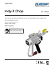
Operation Indy-X Chop GC-1388G Low emission external-mix dispense gun for use with polyester resin and gel coat. For professional use only. Maximum fluid working pressure: 2000 psi (14 MPa, 138 bar) Maximum air pressure: 100 psi (0.7 MPa, 7 bar) Important Safety Instructions Read all warnings and instructions in this manual. Save these instructions.
Contents Warnings........................................................... 3 Important Safety Information.......................... 5 Grounding......................................................... 6 Set-Up................................................................ 7 Parts.................................................................. 8 Assembly Drawings......................................... 9 Pressure Relief Procedure............................ 14 Maintenance...............................
Warnings The following warnings are for the setup, use, grounding, maintenance, and repair of this equipment. The exclamation point symbol alerts you to a general warning and the hazard symbol refers to procedurespecific risk. Refer back to these warnings. Additional, product-specific warnings may be found throughout the body of this manual where applicable. • See Important Safety Information - MEKP, Polyester Resins and Gel-Coats and Spraying and Lamination Operations section of this manual.
Skin Injection Hazard Use with high pressure equipment, generally equipment with pressure rating of 900 psi or higher. There sions of this section. 1) manual guns, 2) UL-1450 compliant equipment 3) automatic guns,/dispense val tion valves, 4) heated hoses. Since the text contains mostly “Do not” statements, the symbols have lines them. Warnings WARNING WARNING SKIN HAZARD SKININJECTION INJECTION HAZARD - Basic High-pressure fluid from gun, hose leaks, or ruptured components will pierce skin.
Important Safety Information Methyl Ethyl Ketone Peroxide (MEKP) MEKP is among the more hazardous materials found in commercial channels. Proper handling of the “unstable (reactive)” chemicals presents a definite challenge to the plastics industry.
Some materials may become self-igniting if applied Grounding too thickly. Read material manufacturer’s warnings and material MSDS. Moisture Sensitivity of Isocyanites This equipment needs to be grounded. Isocyanites (ISO) are catalysts used in two component Ground dispense gun through to a moisture foam andthe polyurea coatings. ISOconnection will react with GlasCraft approved grounded fluid supply hose. (such as humidity) to form small, hard, abrasive crystals, which become suspended in the fluid.
Set-Up Hose Attachment 4. Attach the (stainless steel p/n 20190-00) catalyst hose to the catalyst inlet fitting on the back of the gun. 1. Engage the trigger lock. 5. If the optional fiberglass roving chopper is being used, attach the “red” chopper air line to the chopper air inlet fitting on the back of the gun. Rotate trigger lock to stop the trigger from being activated. 2. Attach the (black p/n 21694-25) material hose to the material inlet fitting on the back of the gun. 3.
Parts Indy-X Chop Dispense Gun 23575-00 Standard Equipment Part Number Description 23575-00 Indy X Chop Dispense Gun GC-1388 User Manual Repair Parts Kits: Part Number 8 Description 23557-00 O-RING KIT 23558-00 MAINTENANCE KIT GC-1388F
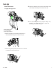
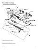
Assembly Drawings 23575-00 Indy X Chop Dispense Gun 2 189018 1 3 1) Catalyst seat assembly p/n: 23544-00 2) Material seat assembly p/n: E-135 3) Material needle valve assembly p/n: 23545-00 GC-1388F 9
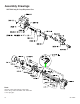
Assembly Drawings 23575-00 Indy X Chop Dispense Gun Note: Use p/n: LPA2-123S and p/n: LPA2-124S when using LPA2-147-XXXX and 23047-XX series spray tips.
Assembly Drawings 23575-00 Indy X Chop Dispense Gun GC-1388F 11
Assembly Drawings 23575-00 Indy X Chop Dispense Gun 12 GC-1388F
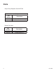
Assembly Drawings 23575-00 Indy X Chop Parts List Part number Description Qty. 11021-41 PIPE PLUG 2 13076-06 O-RING 1 13867-03 O-RING 1 13867-05 O-RING 1 13867-07 O-RING 3 13867-09 O-RING 1 15845-01 BALL DRIVER 1 18383-02 1/4 IN.
Pressure Relief Procedure 4. Verify the Trigger Lock is in the Locked position. To relieve fluid and air pressures: 1. Push down Yellow slide valve, P/N 21402-00 to bleed off air to system. Daily Maintenance 2. Open P/N 21228-00 on catalyst pump to recirculation position. It is recommended that the following service be performed on a daily basis. 1. The Gun is built at the factory with, P/N 21222-00 Lubricate. This is a water soluble lubricate, not affected by most solvents.
everyone in the work area. Maintenance Parts Replacement Procedure To prevent contact with isocyanates, appropriate personal protective equipment, including chemically impermeable gloves, boots, aprons, and goggles, is also required for everyone in the work area. 9. Lightly lubricate all O-Rings with petroleum jelly. Material Self-ignition 10. Check all springs for resilience. They should • K B return quickly to their original (new) length. To we an 11.
Maintenance Needle & Pin Removal Procedures 1. Remove needle collets. (3/8in. Wrench) 2. Remove set screws. (5/64in. Hex Key) 3. Remove needle guard. 4. Remove pins. 5. Remove needle assemblies. (9/16in.
(such as humidity) to form small, hard, abrasive crystals, which become suspended in the fluid. Eventually a film will form on the surface and the ISO will begin to gel, increasing in viscosity. If used, this partially cured ISO will reduce performance and the life of all wetted parts. Maintenance The amount of20507-00 film formation and rate of crystalli-6. a.
Maintenance Needle & Pin Reassemble Procedure 1. Reassemble the needle assemblies to the gun body. Lubricate the o-rings & use teflon tape on the threads. 2. Make sure the gun pins are lubricated and slide them into the gun block and can be seen between the gun block and the back side of the trigger and they both are exposed at the back of the gun block near the catalyst and resin needles. 3. Lock-tite both of the set screws, then assemble them to the needle guard using a 5/64in.
Maintenance Trigger & Needle Guard Readjustment Procedure If you trigger the gun and notice that one needle is activating before the other and not parallel, fine adjustment is needed. 1. Using a 5/64in. hex key adjust the Set Screw which is NOT making gun pin contact when the gun is triggered. Turn the set screw until both needles activate at the same time. Making the needle guard parallel is very important, to prevent LAG-LEAD in the catalyst & resin mix. Set Screws 5/64in.
Maintenance Packing Nut Adjustment Procedure 3 Adjust the packing nuts with a wrench. (3/8in. open end) 1 Remove the trigger from gun. Slide it down and to the side. 2 Slide the gun pins, p/n 23514-00 forward to allow access to the packing nuts.
Options Impingement Dispense Tips Part Number 23005- C4 C5 C6 C7 C8 C9 E4 E5 E6 E7 E8 E9 G4 G5 G6 G7 G8 G9 J4 J5 J6 J7 J8 J9 K4 K5 K6 K7 K8 K9 M4 M5 M6 P4 GC-1388F Orifice 0.040 0.050 0.060 0.070 0.080 0.090 0.040 0.050 0.060 0.070 0.080 0.090 0.040 0.050 0.060 0.070 0.080 0.090 0.040 0.050 0.060 0.070 0.080 0.090 0.040 0.050 0.060 0.070 0.080 0.090 0.040 0.050 0.060 0.040 Min. Max. Min. Max Width (in.) Width (in.) Output (lbs.) Output (lbs.) 7 16.5 5.4 10.02 8.5 15.5 6.36 12.23 7 17 7.31 11.01 7 13 8.
Options Impingement Dispense Tip Reference Chart Part Number Note: Orifice 23047-J1 .012 J2 .014 J3 .022 M1 .012 M2 .014 M3 .022 P1 .012 P2 .014 P3 .022 Use p/n: LPA2-123S and p/n: LPA2-124S when using LPA2-147-XXXX and 23047-XX series spray tips. 22 Airless Dispense Tip Reference Chart Part Number Orifice LPA2-147-1525 0.015 1540 0.015 1550 0.015 1565 0.015 1825 0.018 1840 0.018 1850 0.018 1865 0.018 2125 0.021 2140 0.021 2150 0.021 2165 0.021 2325 0.
Technical Data GC-1388F Category Data Maximum Fluid Working Pressure 2000 psi (13.8 MPa, 138 bar) Maximum Air Inlet Pressure 100 psi (.69 MPa, 6.9 bar) Typical Flow Rate of Pattern Guns Dependent of spray tip Maximum Fluid temperature 120° F (49° C) Air Inlet Size (Chopper) 1/4-18 NPS Male A Component (Catalyst) Inlet Size 1/4 in. Tube B Component (Resin) Inlet Size 1/4-18 NPS Male Solvent Flush 1/4-18 NPS Male Sound Pressure 40.39 dB(A) Sound Power, measured per ISO 94 16-2 56.
Graco Ohio Standard Warranty Graco warrants all equipment referenced in this document which is manufactured by Graco and bearing its name to be free from defects in material and workmanship on the date of sale to the original purchaser for use. With the exception of any special, extended, or limited warranty published by Graco, Graco will, for a period of twelve months from the date of sale, repair or replace any part of the equipment determined by Graco to be defective.